Differential pressure type self-adjusting valve

A self-regulating, differential pressure technology, applied in the direction of turbine/propulsion fuel valve, turbine/propulsion fuel delivery system, engine components, etc. Dissipation and other issues to achieve the effect of improving heat dissipation potential, reducing thermal limitation, and reducing heat accumulation

Active Publication Date: 2020-04-10
SHENYANG AIRCRAFT DESIGN INST AVIATION IND CORP OF CHINA
View PDF5 Cites 2 Cited by
  • Summary
  • Abstract
  • Description
  • Claims
  • Application Information

AI Technical Summary

Problems solved by technology

[0003] The valves in the prior art cannot satisfy the self-regulation function of real-time dynamic changes with the engine fuel consumption load, and it is difficult to ensure a constant flow of fuel to dissipate heat for each on-board system through the fuel thermal management system, and it is also difficult to ensure that this part of the fuel is given priority Engine consumes fuel for adequate heat dissipation

Method used


Image

  • Differential pressure type self-adjusting valve
  • Differential pressure type self-adjusting valve
  • Differential pressure type self-adjusting valve

Examples


Embodiment Construction

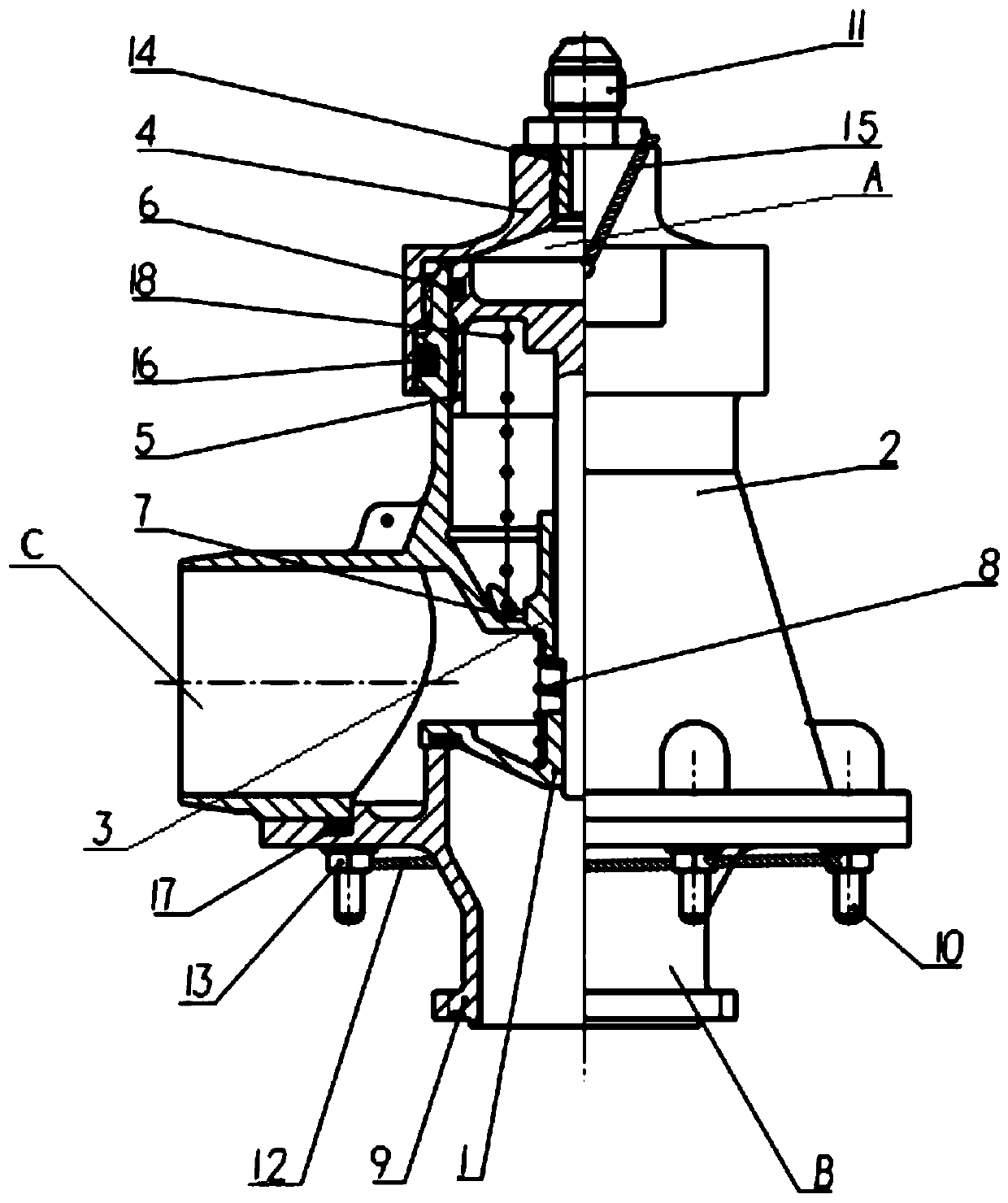
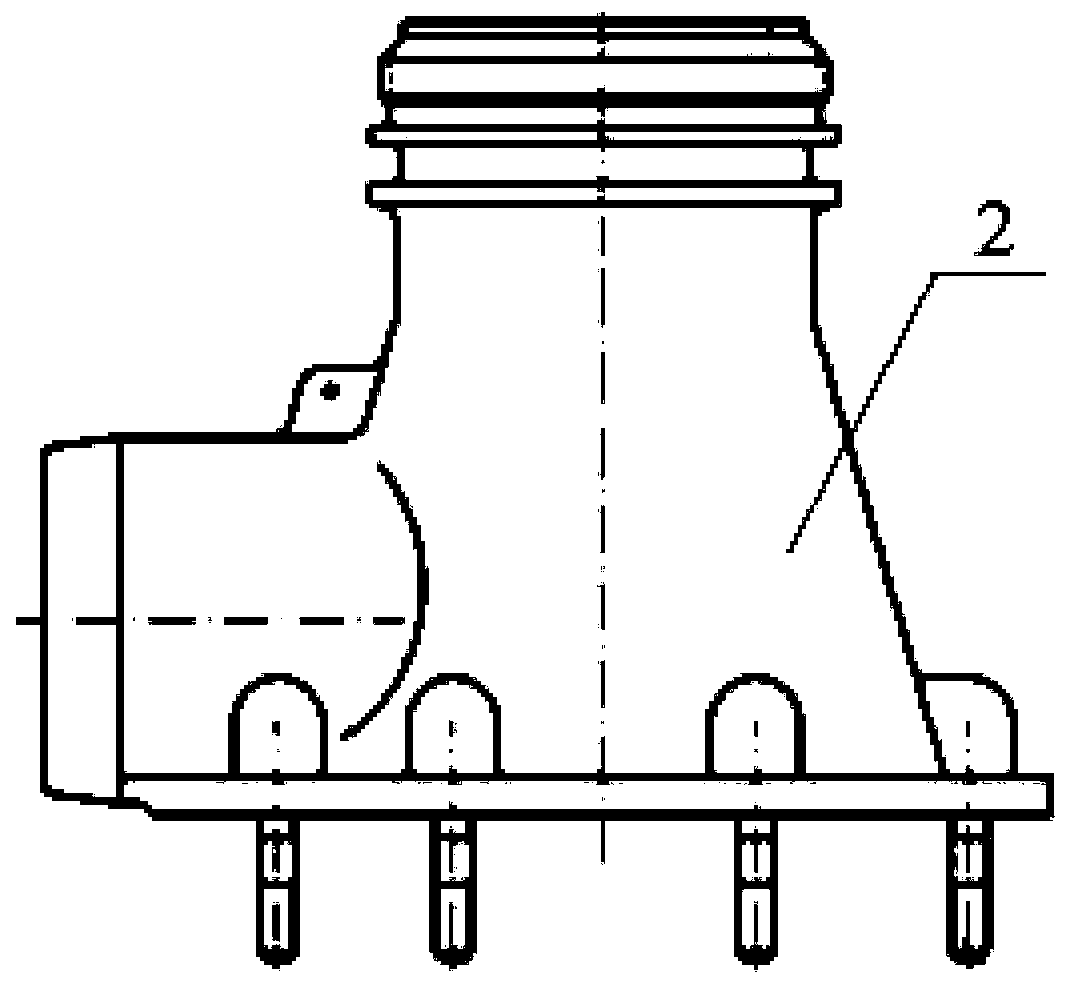
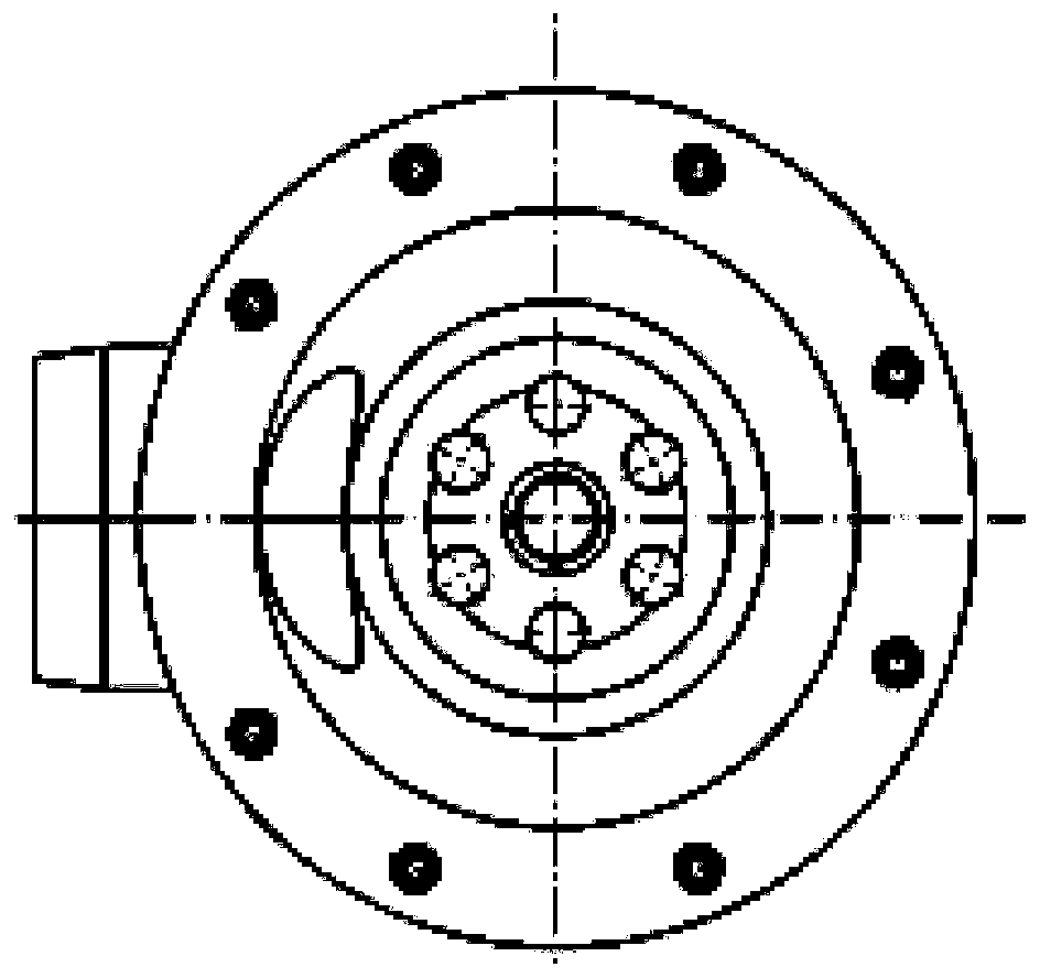
[0036] In order to make the purpose, technical solution and advantages of the application more clear, the technical solution in the embodiment of the application will be described in more detail below in conjunction with the drawings in the embodiment of the application. In the drawings, the same or similar reference numerals denote the same or similar elements or elements having the same or similar functions throughout. The described embodiments are some, but not all, embodiments of the application. The embodiments described below by referring to the figures are exemplary, and are intended to explain the present application, and should not be construed as limiting the present application. Based on the embodiments in this application, all other embodiments obtained by persons of ordinary skill in the art without creative efforts fall within the protection scope of this application. Embodiments of the present application will be described in detail below in conjunction with th...


PUM


Abstract

The invention belongs to the technical field of airplane fuel heat managing, and particularly relates to a differential pressure type self-adjusting valve. The valve comprises a shell, a base, a valvebody, a top cover and a piston. The shell is provided with a first connecting part, a second connecting part and a third connecting part, the third connecting part is provided with a cavity C, a baseis arranged in the shell, the base is connected with the second connecting part, the base is provided with a cavity B, a valve connecting part of the valve body is in abut joint with the base, a center shaft is sleeved with a first spring, one end of the top cover is connected with the first connecting part of the shell, the other end of the top cover is provided with a twisting-in type pipe joint, a piston head of the piston is arranged in the first connecting part of the shell and is in abut joint with the top cover, a cavity A is formed between the head of the piston and the twisting-in type pipe joint, a piston rod penetrates through a first through hole of the base and a second through hole of a valve body, the ladder part of the piston rod is in abut joint with the first spring, thepiston is sleeved with a second spring, and the two ends of the second spring are limited through the head of the piston and the base correspondingly. According to the self-adjusting valve, the opening degree of the valve can be self-adjusted, and the cooling property can be improved.

Description

technical field [0001] The application belongs to the technical field of aircraft fuel thermal management, and in particular relates to a differential pressure self-regulating valve. Background technique [0002] In the technical field of aircraft fuel system thermal management, according to the heat dissipation requirements of on-board hydraulic systems, environmental control and other systems, a fuel heat sink with a relatively constant flow rate is often required to dissipate heat. After passing through various types of heat exchangers to dissipate the heat of each airborne system, the fuel is heated up, according to the design principles of reducing internal heat accumulation, improving the aircraft’s heat dissipation potential, giving priority to engine combustion heat dissipation, and realizing dynamic management of heat sinks. When the fuel consumption rate is high, all the fuel is taken away by the engine combustion; when the fuel consumption rate is low, the excess ...

Claims


Application Information

Patent Timeline
IPC IPC(8): F02C7/232
CPCF02C7/232
Inventor 赵营丁磊丁恩良周梓桐常宏亮
Owner SHENYANG AIRCRAFT DESIGN INST AVIATION IND CORP OF CHINA
Why Eureka
Try Eureka