
Method for calculating temperature field of laser ablation carbon fiber target material

A technology of laser ablation and calculation method, which is applied in calculation, computer-aided design, design optimization/simulation, etc., can solve the problem of not considering the thermal physical properties of the element sequence stripped carbon fiber target, inaccurate calculation of burn-through time, carbon fiber temperature field, etc. Problems such as low distribution accuracy can achieve the effect of avoiding abnormal temperature, reducing error and improving accuracy

Active Publication Date: 2020-04-10
UNIV OF ELECTRONICS SCI & TECH OF CHINA
View PDF9 Cites 7 Cited by
  • Summary
  • Abstract
  • Description
  • Claims
  • Application Information

AI Technical Summary

Problems solved by technology

[0008] The purpose of the present invention is to solve the problem that in the prior art, when calculating the temperature field and burn-through time of the laser ablation carbon fiber target, the delamination of the element sequence after the surface of the carbon fiber target exceeds the threshold temperature of self-vaporization and the change with temperature are not considered. The thermophysical properties of the carbon fiber target caused the low accuracy of the carbon fiber temperature field distribution and the inaccurate calculation of the burn-through time in the numerical calculation process. A calculation method for the temperature field of the laser ablation carbon fiber target is provided.

Method used

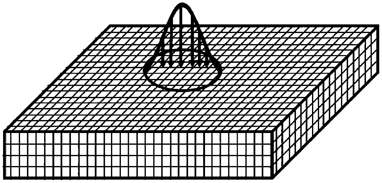
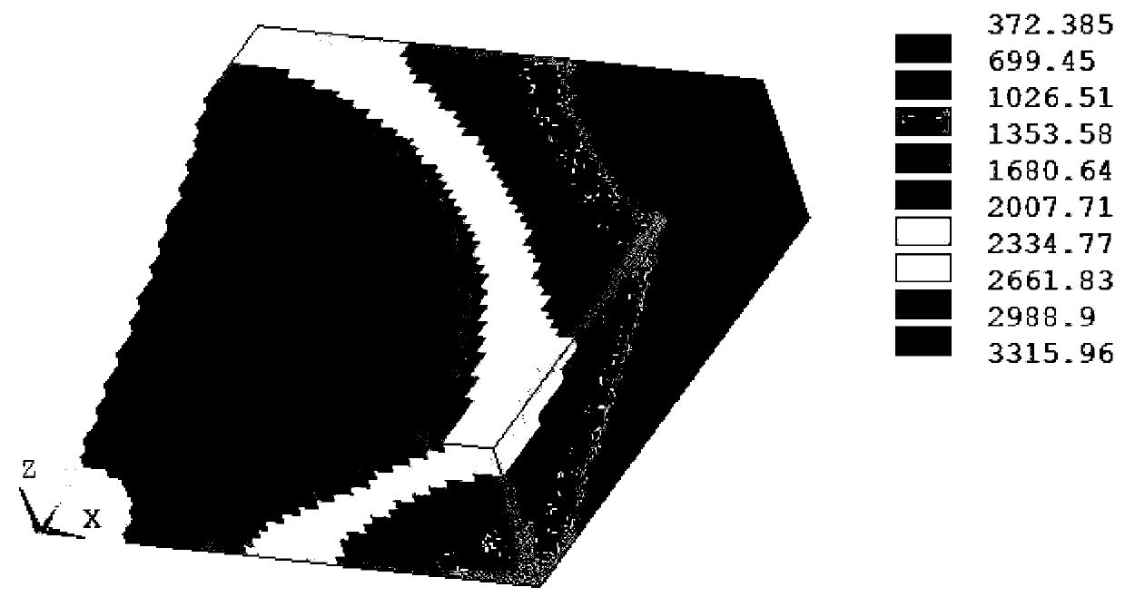

Image

  • Method for calculating temperature field of laser ablation carbon fiber target material
  • Method for calculating temperature field of laser ablation carbon fiber target material
  • Method for calculating temperature field of laser ablation carbon fiber target material

Examples


Embodiment 1

[0055] In the prior art, when calculating the temperature field and burn-through time of laser ablation carbon fiber targets, the carbon fiber material is usually regarded as an isotropic medium, and its thermophysical parameters are also treated as constants. During the calculation process, the two-dimensional The temperature field is rotated to directly obtain the three-dimensional temperature field, ignoring the fact that the surface of the carbon fiber target is peeled off, resulting in a large error in the calculation of the temperature field and burn-through time of the carbon fiber target. The inventors of the present application found in the research: (1) the thermal physical parameters of the carbon fiber target should not be treated as constants, but should be regarded as values ​​that vary with temperature; (2) for the laser ablation process The unit whose surface temperature of the carbon fiber target exceeds the temperature threshold should be peeled off. In order...


PUM


Abstract

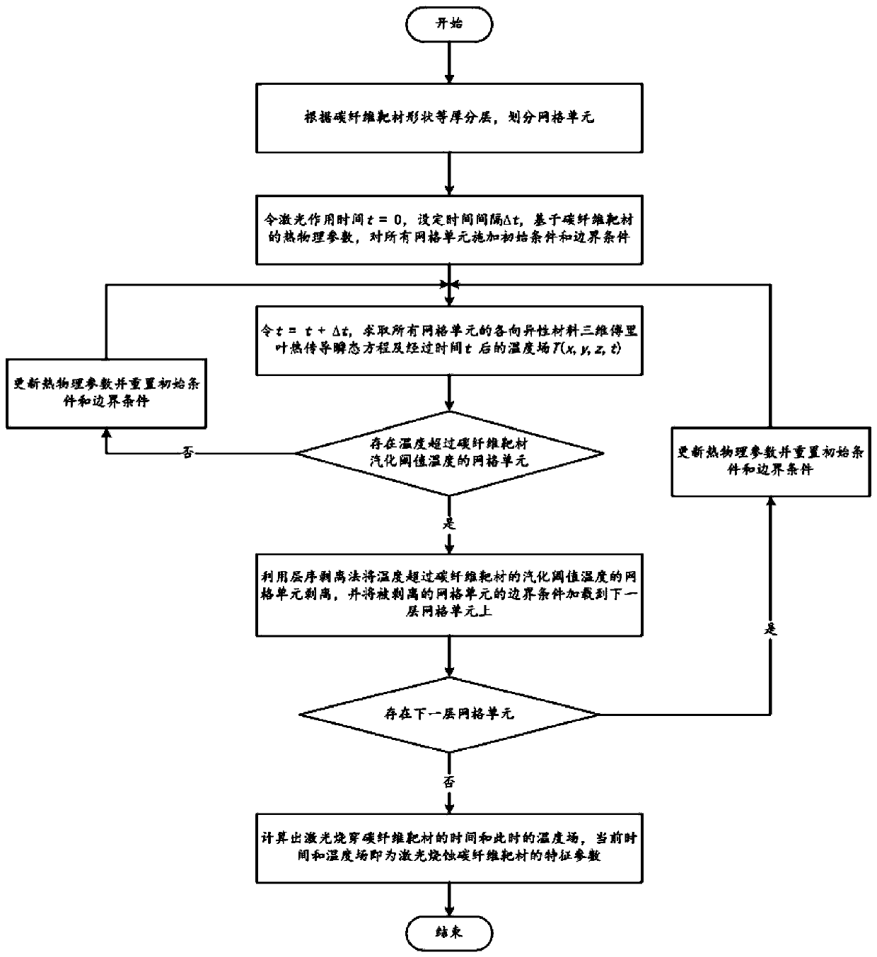
The invention discloses a method for calculating a temperature field of a laser ablation carbon fiber target material, and relates to the field of laser damage effect research, and the method comprises the following steps: 1, carrying out the equal-thickness layering according to the shape of the carbon fiber target material, and dividing grid units; 2, setting the laser action time t to be equalto 0, setting a time interval delta t, and applying an initial condition and a boundary condition to the unit according to the thermophysical parameters of the carbon fiber target material; 3, settingt= t + delta t, solving three-dimensional heat conduction transient equations of anisotropic materials of all units, and calculating a target material temperature field after time t; 4, if a grid unit with the temperature exceeding the vaporization threshold temperature of the carbon fiber target exists, vaporizing the unit according to a meta-order stripping method, loading the corresponding boundary condition to the next layer of unit, and then executing the step 5; 5, traversing the grid units: judging whether a next layer of unit exists, if yes, adjusting the thermophysical parameters ofthe target material, updating the boundary condition and the initial condition, and then executing the step 3; otherwise, determining a fact that the time and the temperature field are the characteristic parameters of the laser damaged carbon fiber target material.

Description

technical field [0001] The invention relates to the field of laser damage effect research, in particular to a calculation method for the temperature field of a laser ablation carbon fiber target, which is used for calculating the real-time temperature field and burn-through time of a high-energy laser damage carbon fiber target. Background technique [0002] In recent years, the damage of UAVs and other targets by high-energy laser weapons has become a research hotspot. Among them, the numerical calculation of laser damage plays a very important role in the pre-war prediction and wartime monitoring of laser weapons destroying UAVs. The research on laser irradiation target materials at home and abroad mainly focuses on metal shells, and there are few studies on fiber-reinforced composite materials, especially carbon fiber composite materials for laser irradiation, while the materials used in drones are mainly composed of carbon fiber composite materials. . Carbon fiber compo...

Claims


Application Information

Patent Timeline
IPC IPC(8): G06F30/23G06F119/08
Inventor 杨春平邓湘奇李伟韦炎斌孔轩段志伟周方方彭真明
Owner UNIV OF ELECTRONICS SCI & TECH OF CHINA
Learn More