Double-cage rotor punching sheet, double-cage rotor and motor
A cage-type rotor and punching technology, which is applied in the field of motors, can solve the problems of low magnetic permeability, narrow and long guide bar structure of single-cage rotor, and low magnetic permeability of double-cage rotor punching, so as to improve the magnetic permeability, High performance and operating efficiency, improvement of yoke deficiencies
- Summary
- Abstract
- Description
- Claims
- Application Information
AI Technical Summary
Problems solved by technology
Method used
Image

Examples
Embodiment Construction
[0048] In order to make the object, technical solution and advantages of the present invention more clear, the present invention will be further described in detail below in conjunction with the examples, but the protection scope of the present invention is not limited to the following specific examples.
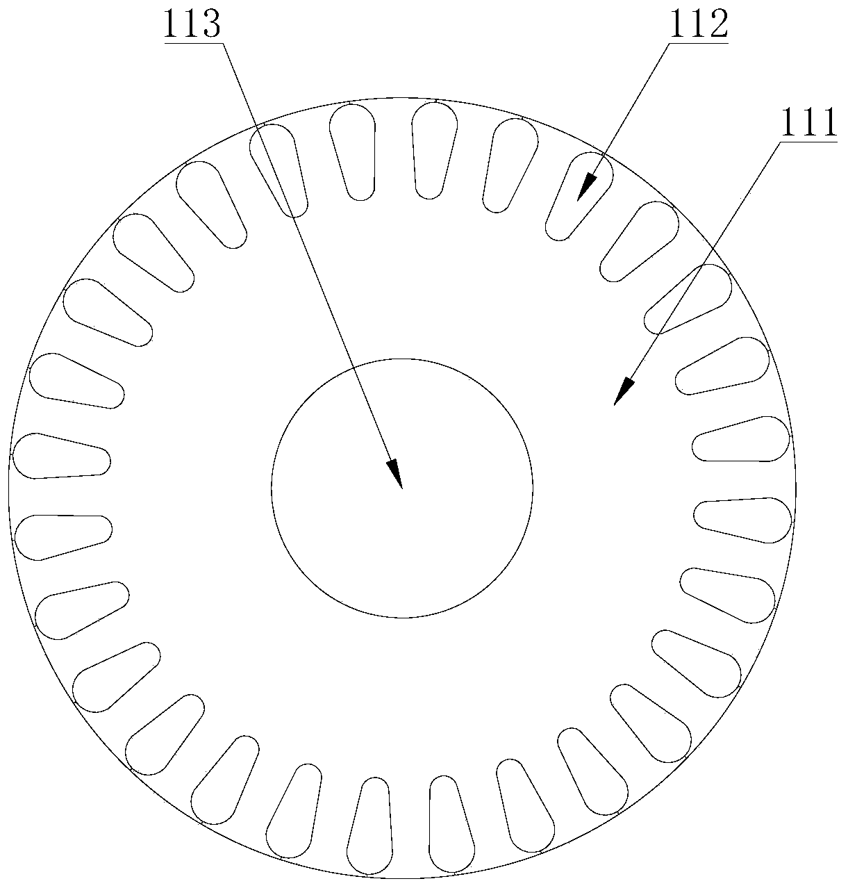
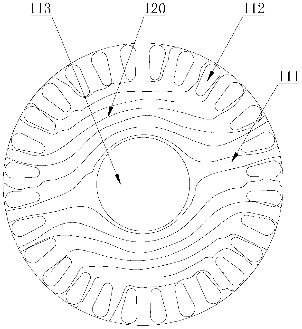
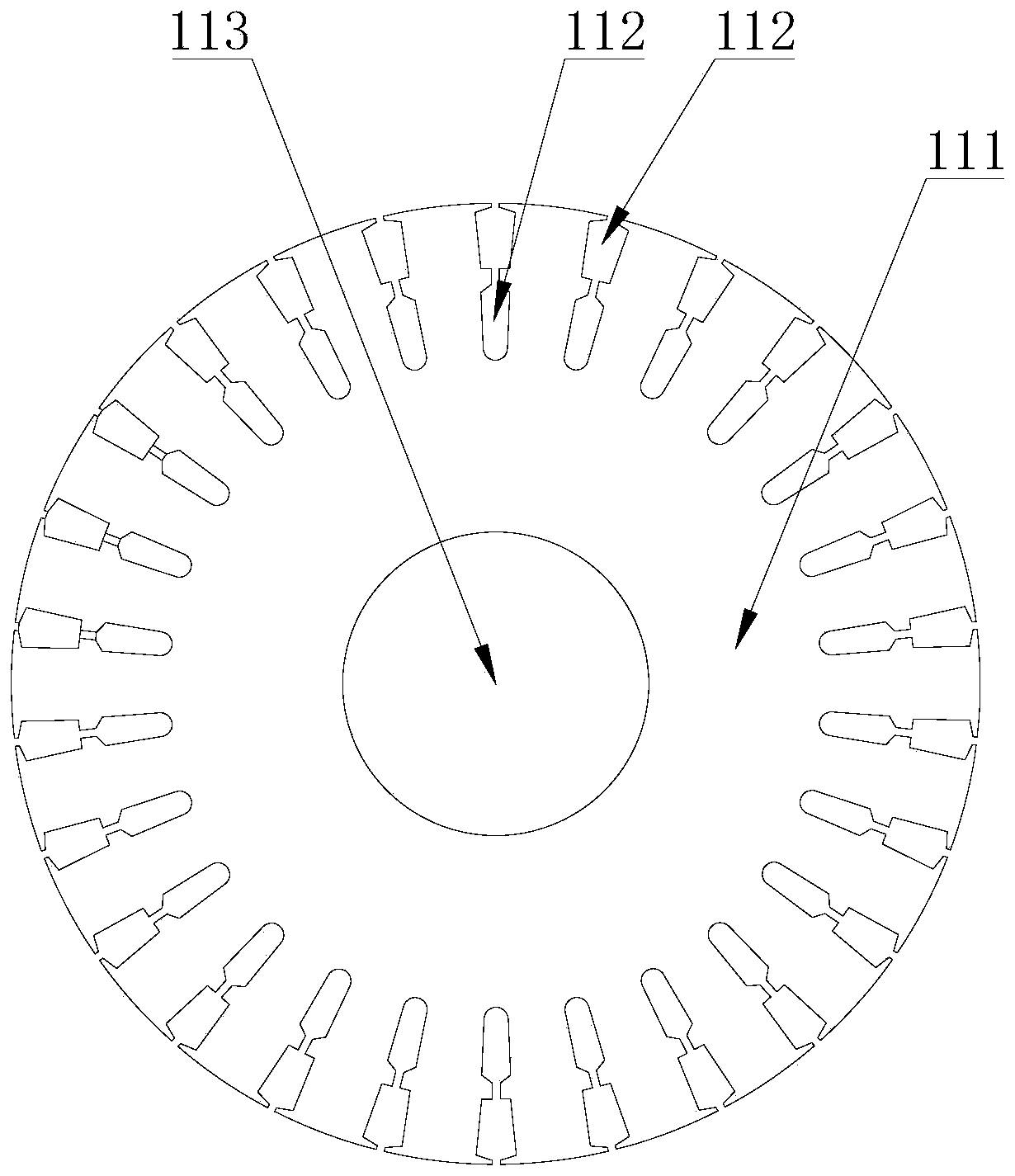
[0049] refer to Figure 5-24 , this embodiment discloses a double-cage rotor 1000 punched sheet, including a silicon steel sheet 111, the silicon steel sheet 111 has a certain degree of magnetic permeability, the silicon steel sheet 111 is a circular sheet, and the silicon steel sheet 111 is provided with two layers of rotor slots, The two-layer rotor slots are punched and formed by the silicon steel sheet 111. The two-layer rotor slots are arranged at intervals along the radial direction of the silicon steel sheet 111. The two-layer rotor slots include the outer rotor slot and the inner rotor slot. The outer rotor slot includes several first rotor slots. 114, several first ...
PUM
 Abstract
Description
Claims
Application Information
 - R&D
- Intellectual Property
- Life Sciences
- Materials
- Tech Scout
- Unparalleled Data Quality
- Higher Quality Content
- 60% Fewer Hallucinations
Browse by: Latest US Patents, China's latest patents, Technical Efficacy Thesaurus, Application Domain, Technology Topic, Popular Technical Reports.
© 2025 PatSnap. All rights reserved.Legal|Privacy policy|Modern Slavery Act Transparency Statement|Sitemap|About US| Contact US: help@patsnap.com