Supercharge Your Innovation With Domain-Expert AI Agents!

Switching converter

A technology of switching converters and converters, which is applied to instruments, converting DC power input to DC power output, and adjusting electrical variables. It can solve the problems of many components and unfavorable integration, and achieve the effect of reducing ripple.

Active Publication Date: 2020-04-10
MORNSUN GUANGZHOU SCI & TECH
View PDF9 Cites 0 Cited by
  • Summary
  • Abstract
  • Description
  • Claims
  • Application Information

AI Technical Summary

Problems solved by technology

In terms of input zero-ripple patents, there are related patents in China. By adding inductors and capacitors on the basis of the basic topology, the input current zero-ripple is realized. There are many components added, which is not conducive to integration.

Method used


Image

  • Switching converter
  • Switching converter

Examples


Embodiment Construction

[0017] In order to make the object, technical solution and advantages of the present invention more clear, the present invention will be further described in detail below in conjunction with the accompanying drawings and embodiments. It should be understood that the specific embodiments described here are only used to explain the present invention, not to limit the present invention.

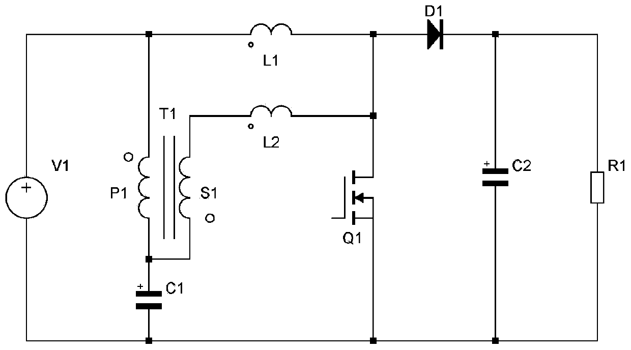
[0018] figure 1 It is a schematic circuit diagram of the switching converter of the present invention after connecting the input voltage source and the load, including the input voltage source V1, the transformer T1, the inductors L1 and L2, the switching tube Q1, the diode D1, the capacitors C1 and C2, and the load resistor R1;

[0019] The connection relationship of this embodiment is as follows:

[0020] The positive end of the input voltage source V1 is electrically connected with the same-named end of the primary winding P1 of the transformer T1 and one end of the inductance L1, the opposi...


PUM


Abstract

The present invention provides a switching converter. An inductor, a transformer and a capacitor are additionally arranged on the basis of a common boost circuit, and the change of the current of thetransformer is utilized to counteract the change of the current of an original inductor, so that the zero ripple input of the whole converter can be realized, and the low-frequency conduction noise isreduced. The voltage of the added transformer is zero in a steady state, so that a small-size magnetic core can be adopted, the space occupied by the device is reduced, and a basis is provided for integrally realizing a small-size power supply.

Description

technical field [0001] The present invention relates to a switching converter, in particular to a step-up switching converter. Background technique [0002] Switching power supplies are widely used due to their small size and high efficiency. Since the switching power supply will cause large current ripple and noise during the switch on and off process, which will cause external interference and affect the normal operation of other devices. Based on this shortcoming of switching power supply, it cannot be used in occasions that are sensitive to power supply ripple noise. [0003] In order to reduce interference, some scholars have reduced the ripple of the input current of the switching power supply, thereby reducing the interference of the fundamental frequency and weakening the interference of the power supply to the power supply network. In terms of input zero ripple patents, there are related patents in China. By adding inductors and capacitors on the basis of the basi...

Claims


Application Information

Patent Timeline
IPC IPC(8): H02M3/155H02M1/14
CPCH02M1/14H02M3/155
Inventor 王志燊钟辉
Owner MORNSUN GUANGZHOU SCI & TECH
Features
  • R&D
  • Intellectual Property
  • Life Sciences
  • Materials
  • Tech Scout
  • Unparalleled Data Quality
  • Higher Quality Content
  • 60% Fewer Hallucinations
Learn More