Scraper type evaporator

An evaporator and scraper-type technology, which is applied in the field of scraper-type evaporators, can solve the problems of reducing the life of the scraper and the cylinder, requiring very high precision, and reducing the quality of the feed liquid, etc., to increase the operating time, increase the concentration quality, reduce The effect of collision probability

Active Publication Date: 2020-04-14
济宁市邦达煤化工有限公司
View PDF4 Cites 1 Cited by
  • Summary
  • Abstract
  • Description
  • Claims
  • Application Information

AI Technical Summary

Problems solved by technology

[0003] The working principle of the existing scraped evaporator is as follows Figure 4 As shown, the feed liquid is added from the upper part of the evaporator along the tangential direction, and then falls into the distribution tray. Due to gravity, centrifugal force and the action of the rotating scraper, the solution forms a downward-swirling film on the inner wall of the evaporator, and is absorbed during the process. Evaporated and concentrated, the finished liquid is discharged at the bottom. In order to scrape the material liquid, the gap between the scraper and the cylinder in actual installation is only 1-1.5 mm, which makes the accuracy requirements between the scraper and the cylinder very high. The upper rotating shaft is always in a rotating state, causing the sleeve at the bottom of the rotating shaft to be easily worn, resulting in a slight displacement and a slight gap when the rotating shaft rotates. In addition, the inner wall of the cylinder is prone to scaling, resulting in the scraper and the cylinder The direct collision between the scraper will cause the scraper to scratch the inner wall of the cylinder, and the scraper will also be gradually worn. The iron filings generated after the wear will fall to the bottom of the evaporator and mix in the feed liquid under the influence of gravity, resulting in concentrated feed. The liquid contains a lot of impurities, which reduces the quality of the feed liquid. Since there are multiple scrapers installed on the rotating shaft, and the scrapers are deformed after wear, the weight and shape of the scrapers on the rotating shaft will change, and the scrapers are not on the left and right. Symmetrical, left and right shaking occurs when rotating, which drives the rotating shaft to shake, aggravates the wear of the shaft sleeve, and further causes the scraper and the inner wall to contact again, reducing the life of the scraper and the cylinder

Method used


Image

  • Scraper type evaporator
  • Scraper type evaporator
  • Scraper type evaporator

Examples


Embodiment Construction

[0018] The following will clearly and completely describe the technical solutions in the embodiments of the present invention with reference to the accompanying drawings in the embodiments of the present invention. Obviously, the described embodiments are only some, not all, embodiments of the present invention. Based on the embodiments of the present invention, all other embodiments obtained by persons of ordinary skill in the art without making creative efforts belong to the protection scope of the present invention.

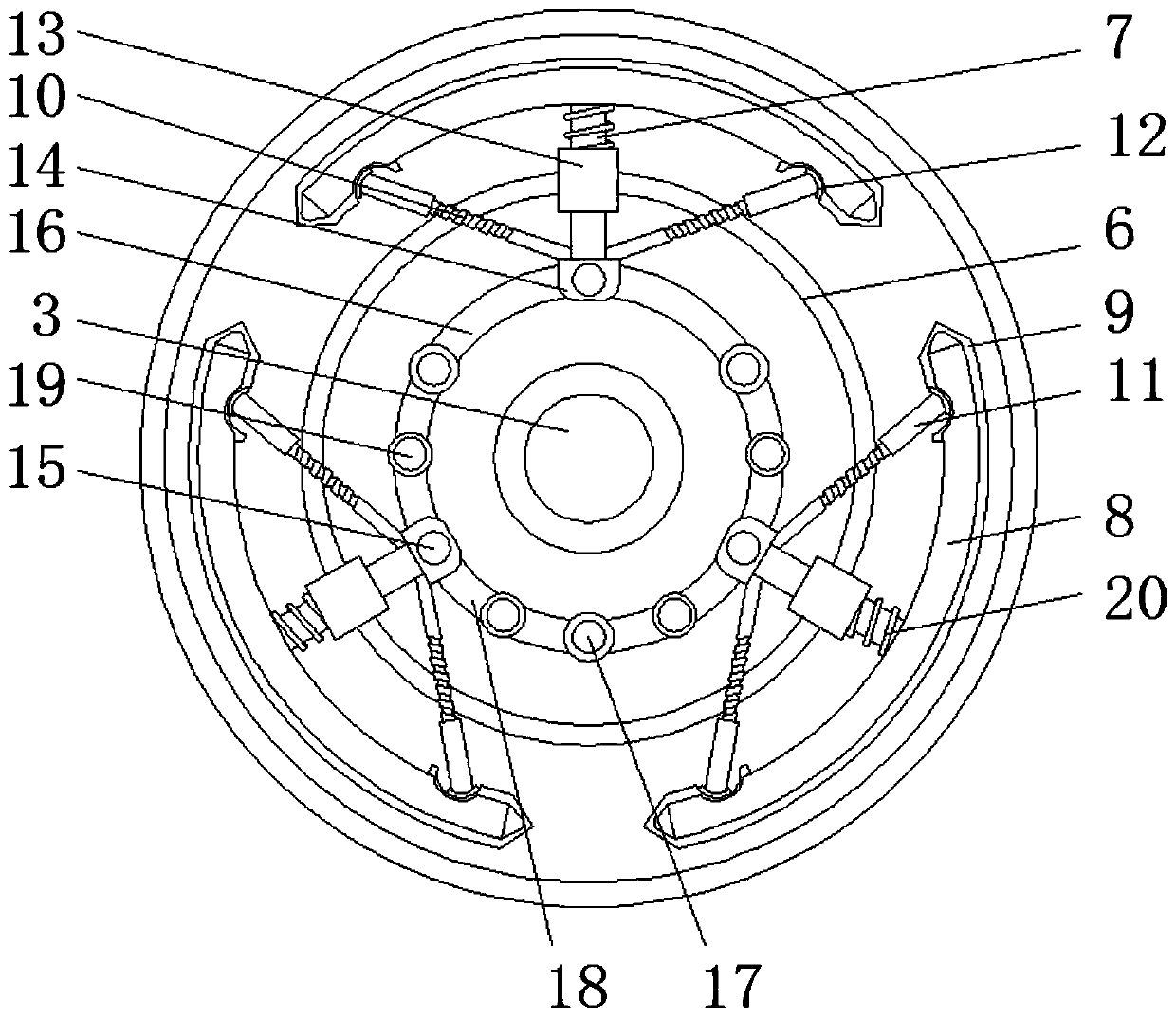
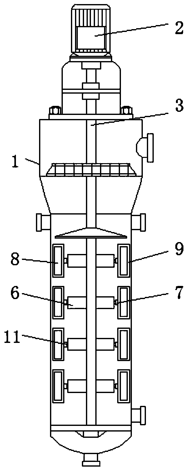
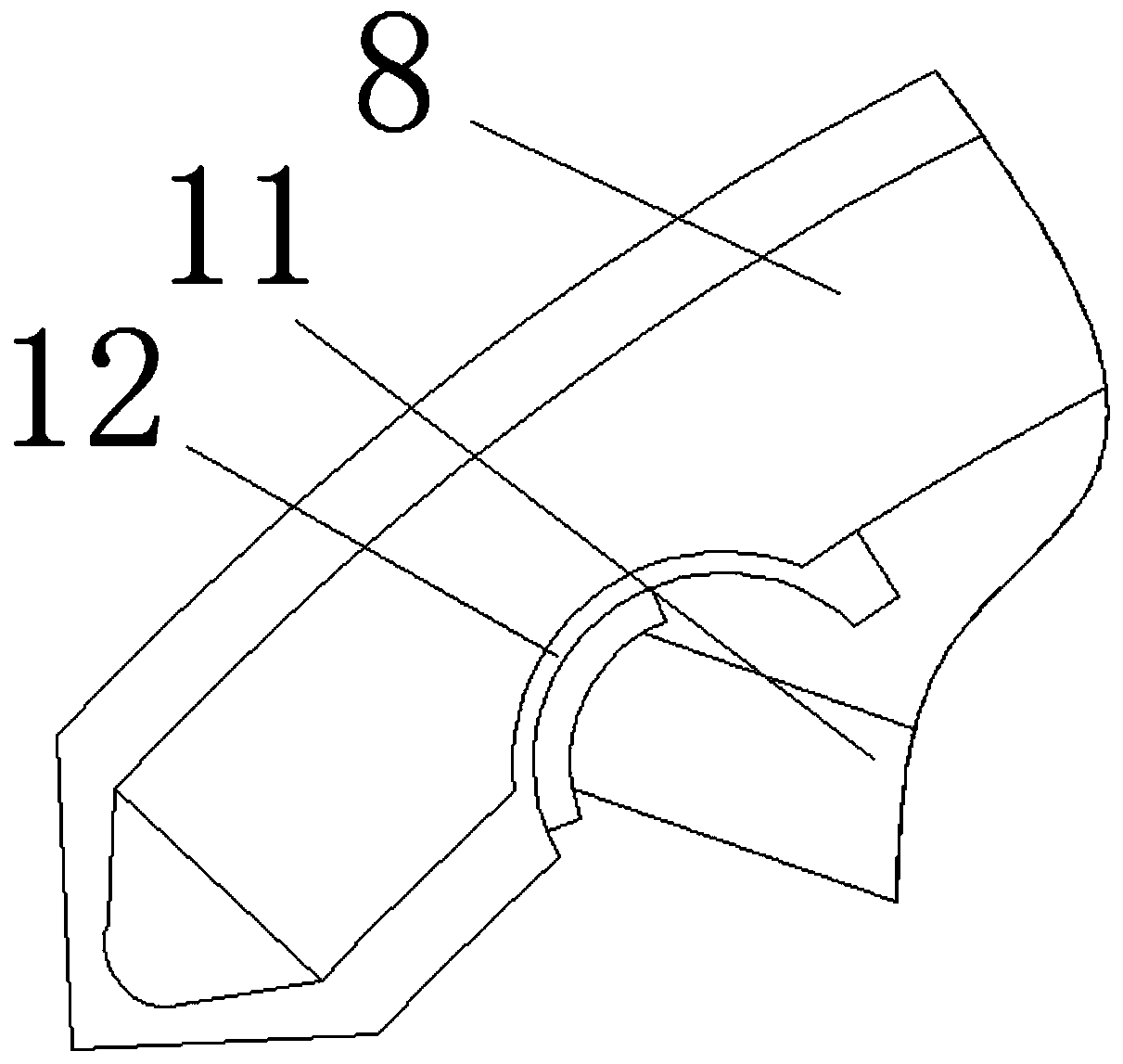
[0019] see Figure 1-4 , a scraper-type evaporator, including a cylinder 1, a motor 2, a rotating shaft 3, a support frame 4, and a scraper 5, the motor 2 is installed on the top of the cylinder 1, the rotating shaft 3 is installed on the motor 2, and the support frame 4 Installed on the rotating shaft 3, the scraper 5 is installed on the support frame 4, the bearing plate 6 is installed on the rotating shaft 3, the supporting rod 7 is installed on the bearing...


PUM


Abstract

The invention relates to the technical field of evaporators. The invention discloses a scraper type evaporator. The scraper type evaporatorcomprises a cylinder, a motor, a rotating shaft, a supportingframe and a scraper blade, the motor is installed at the top of the cylinder, the rotating shaft is installed on the motor, the supporting frame is installed on the rotating shaft, the scraper bladeis installed on the supporting frame, a bearing plate is installed on the rotating shaft, a supporting rod is installed on the bearing plate, and an arc-shaped plate located outside the bearing plateis installed at the end of the supporting rod. The arc-shaped plate is matched with an arc-shaped sleeve; rigid contact between the traditional scraper and the inner wall is optimized aselastic contact, when the arc-shaped plate collides with thecylinder; the arc-shaped plate can be retracted instantaneously, so that the diameter of the arc-shaped plate is reduced, the strength of friction betweenthe arc-shaped plate and the cylinder is reduced, the durability of the arc-shaped plate and the cylinder is improved, and meanwhile, through cooperation of a positioning seat, a positioning rod, a positioning plate, the rotating shaft, a sliding plate and a positioning pin, after one arc-shaped plate is collided, all arc-shaped edges can be driven to shrink synchronously.

Description

technical field [0001] The invention relates to the technical field of evaporators, in particular to a scraper type evaporator. Background technique [0002] The scraper type evaporator is equipped with a heating steam jacket outside the shell, and a rotatable scraper is installed inside. The scraper is driven by the rotating shaft in the center of the cylinder to scrape the steam on the cylinder. [0003] The working principle of the existing scraped evaporator is as follows Figure 4 As shown, the feed liquid is added from the upper part of the evaporator along the tangential direction, and then falls into the distribution tray. Due to gravity, centrifugal force and the action of the rotating scraper, the solution forms a downward-swirling film on the inner wall of the evaporator, and is absorbed during the process. Evaporated and concentrated, the finished liquid is discharged at the bottom. In order to scrape the material liquid, the gap between the scraper and the cylin...

Claims


Application Information

Patent Timeline
Patent Type & Authority Applications(China)
IPC IPC(8): B01D1/22B01D1/30
CPCB01D1/225
Inventor 杨香兰
Owner 济宁市邦达煤化工有限公司
Why Eureka
Try Eureka