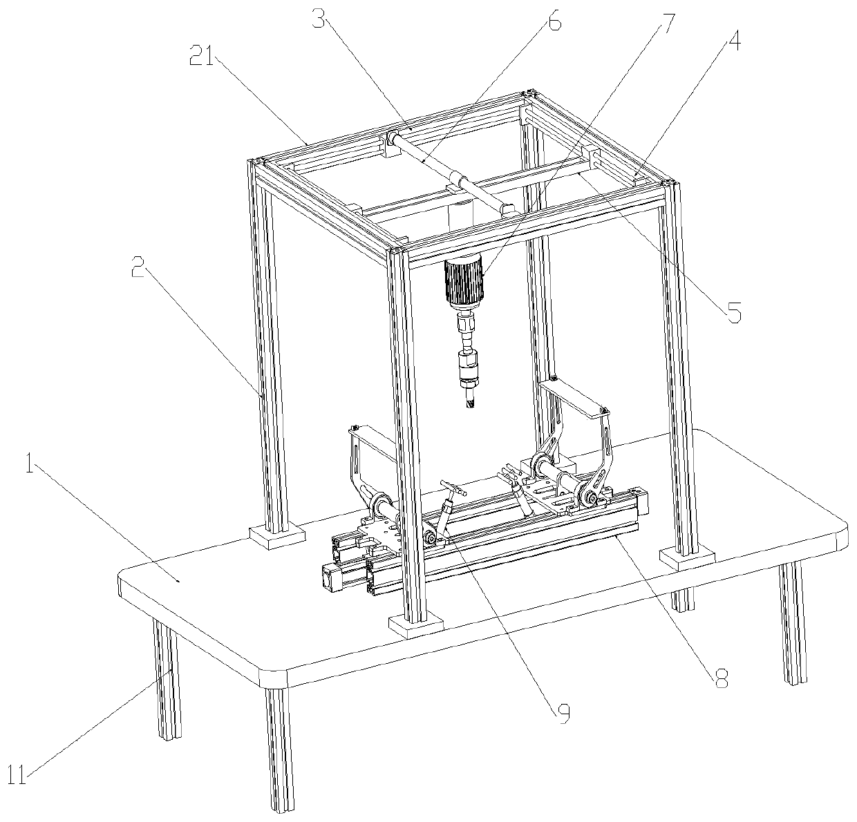
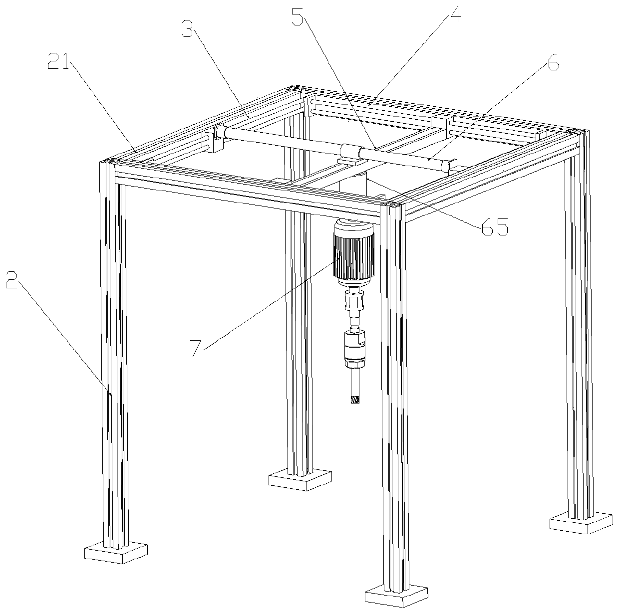
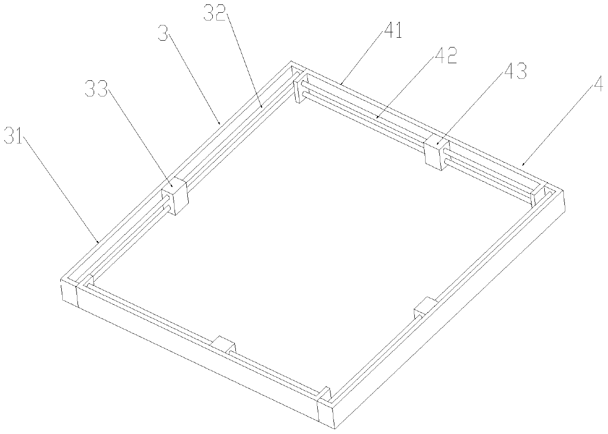
Automatic machining process and equipment for crankcase stator surface

An automatic processing and crankcase technology, applied in metal processing equipment, metal processing machinery parts, positioning devices, etc., can solve the problems of workpiece rework, low clamping firmness, high equipment cost, etc., and achieve convenient tool change and clamping effect Good, the effect of improving work efficiency

Active Publication Date: 2020-04-14
安徽华旦机械制造有限公司
View PDF6 Cites 5 Cited by
  • Summary
  • Abstract
  • Description
  • Claims
  • Application Information

AI Technical Summary

Problems solved by technology

[0003] Most of the existing clamping devices are positioned vertically or horizontally. When processing the crankcase stator surface, the clamping firmness is often low, and the workpiece is prone to fall off during processing, resulting in the workpiece needing to be reworked or scrapped directly.
[0004] At the same time, the existing crankcase is processed by machine tools, the equipment cost is high, and it is not suitable for small-scale production
When the number of workpieces is small, manual operation is required. For example, when drilling, milling, and spherical processing, it is necessary to change the tool frequently, and it is necessary to manually find the positioning point for processing during processing. Long-term work will also increase the fatigue strength of the operator.

Method used


Image

  • Automatic machining process and equipment for crankcase stator surface
  • Automatic machining process and equipment for crankcase stator surface
  • Automatic machining process and equipment for crankcase stator surface

Examples


Embodiment Construction

[0044] The following will clearly and completely describe the technical solutions in the embodiments of the present invention with reference to the accompanying drawings in the embodiments of the present invention. Obviously, the described embodiments are only some, not all, embodiments of the present invention. Based on the embodiments of the present invention, all other embodiments obtained by persons of ordinary skill in the art without creative efforts fall within the protection scope of the present invention.

[0045] In describing the present invention, it is to be understood that the terms "opening", "upper", "lower", "thickness", "top", "middle", "length", "inner", "surrounding" etc. Indicating orientation or positional relationship is only for the convenience of describing the present invention and simplifying the description, and does not indicate or imply that the components or elements referred to must have a specific orientation, be constructed and operated in a sp...


PUM


Abstract

The invention discloses an automatic machining process and equipment for a crankcase stator surface. A to-be-machined crankcase stator surface is placed at the upper end of a second air cylinder in anupward facing mode, a hydraulic cylinder is driven, the end part of a connecting plate moves back and forth, a rotating shaft rotates to drive the connecting plate to rotate, the bottom end of a clamping plate is in contact with the crankcase stator surface, the crankcase stator surface is clamped, the second air cylinder is driven, a second air pressure rod moves upwardly, clamping for machiningthe crankcase stator surface is achieved through cooperation of the clamping plate and a fixing rod, the clamping effect on the arc-shaped bottom surface of the crankcase is good through the clampingmode that a sponge body is matched with the clamping plate, and the phenomenon that a workpiece deviates or falls off is avoided. Meanwhile, a first linear electric cylinder and a second linear electric cylinder are arranged, the first linear electric cylinder, the second linear electric cylinder are driven, the connecting rod can move to any position in the supporting cross rod, then the motor and the first air cylinder are driven to move in all directions, automatic operation is achieved during milling, no dead angle exists during milling, and the working efficiency is improved.

Description

technical field [0001] The invention relates to the field of automatic processing of a crankcase stator surface, in particular to an automatic processing technology and equipment for a crankcase stator surface. Background technique [0002] The crankcase of the compressor is an important part of the compressor. The crankcase of the compressor is a box-like part. Usually, the outer shape is not regular, and the bottom is an arc surface. When machining the crankcase, it needs to be fixed and clamped to prevent position deviation during machining. [0003] Most of the existing clamping devices are positioned vertically or horizontally. When machining the crankcase stator surface, the clamping firmness is often low, and the workpiece is prone to fall off during processing, resulting in the workpiece needing to be reworked or directly scrapped. [0004] Simultaneously, the existing crankcase is processed by machine tools, the equipment cost is high, and it is not suitable for sm...

Claims


Application Information

Patent Timeline
Patent Type & Authority Applications(China)
IPC IPC(8): B23P15/00B23Q1/25B23Q3/08B23Q5/26B23Q5/34
CPCB23P15/00B23Q1/25B23Q3/08B23Q5/26B23Q5/34
Inventor 文勤金礼黄长青马权钱
Owner 安徽华旦机械制造有限公司
Why Eureka
Try Eureka