Ceramic tile cutting device

A technology for cutting equipment and ceramic tiles, which is applied in metal processing equipment, grinding/polishing equipment, manufacturing tools, etc. It can solve the problems of cumbersome manual feeding operations, inaccurate feeding, and low safety, so as to improve cutting efficiency, Ease of operation and improved safety

Active Publication Date: 2020-04-14
广东长海建设工程有限公司
View PDF11 Cites 2 Cited by
  • Summary
  • Abstract
  • Description
  • Claims
  • Application Information

AI Technical Summary

Problems solved by technology

[0003] In order to overcome the shortcomings of low efficiency, cumbersome manual feeding operation, low safety, and inaccurate feeding leading to cutting errors when manually measuring and cutting ceramic tiles, the technical problem of the present invention is to provide a working Ceramic tile cutting equipment with high efficiency, automatic feeding of ceramic tiles, ensuring the safety of operators, and accurate cutting

Method used


Image

  • Ceramic tile cutting device
  • Ceramic tile cutting device
  • Ceramic tile cutting device

Examples


Embodiment 1

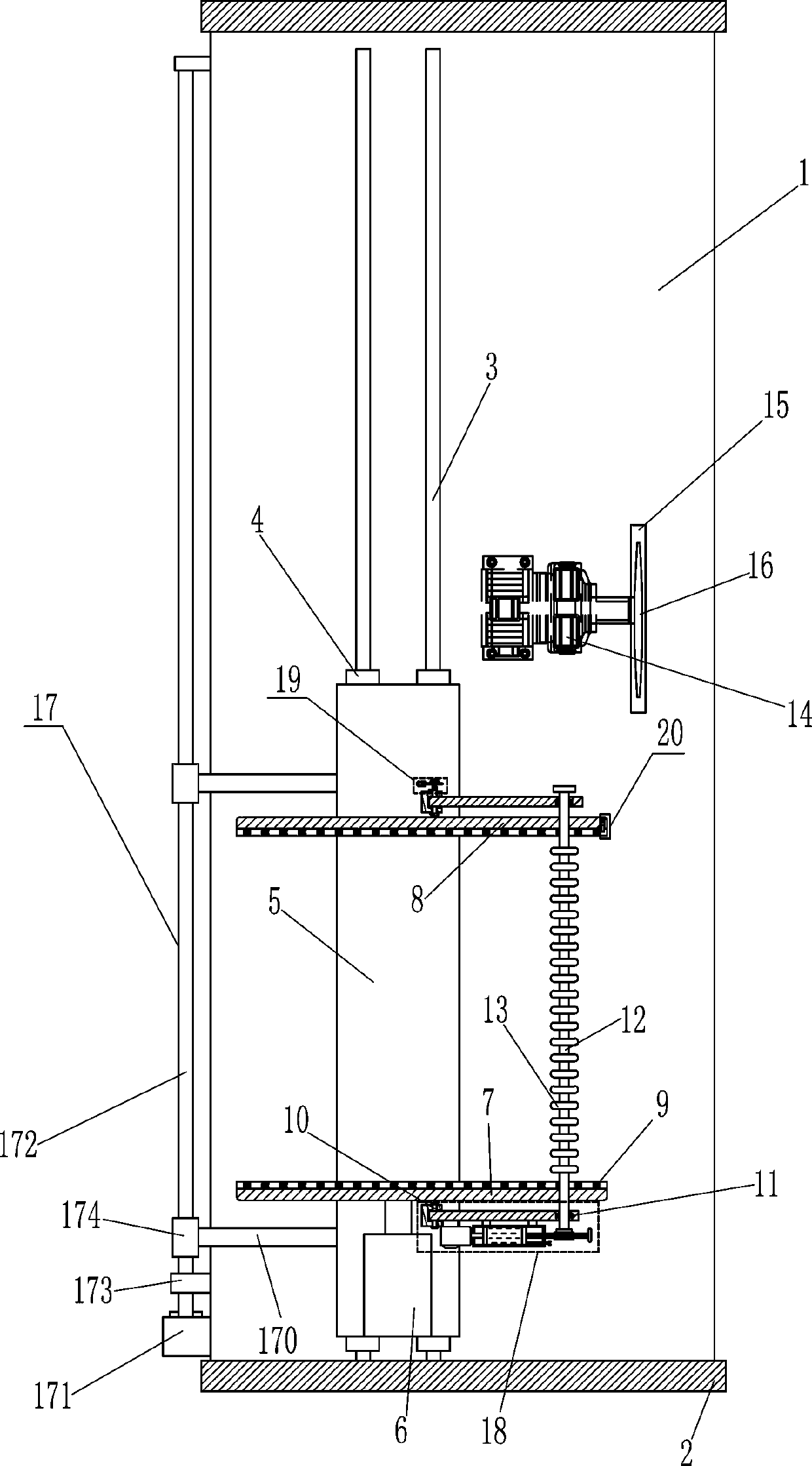
[0017] A tile cutting equipment such as figure 1 As shown, it includes a bottom plate 1, a baffle plate 2, a slide rail 3, a first slider 4, a mounting seat 5, a first cylinder 6, a moving deck 7, a fixed deck 8, a pulley 9, a rotating shaft 10, and a torsion spring 101 , swing bar 11, transmission rod 12, rubber roller 13, first motor 14, emery wheel 16 and driving mechanism 17, base plate 1 front and rear sides are connected with baffle plate 2, base plate 1 is connected with baffle plate 2 by the mode of welding connection, base plate 1 The left side of the top is symmetrically provided with a slide rail 3, the slide rail 3 is provided with a first slider 4, the top of the first slider 4 on the left and right sides is connected with a mounting seat 5, and the top front side of the mounting seat 5 is provided with a first cylinder 6 , the telescopic rod of the first cylinder 6 is connected with a movable deck 7, and the rear side of the top of the mounting base 5 is provided...

Embodiment 2

[0019] A tile cutting equipment such as figure 1 As shown, it includes a bottom plate 1, a baffle plate 2, a slide rail 3, a first slider 4, a mounting seat 5, a first cylinder 6, a moving deck 7, a fixed deck 8, a pulley 9, a rotating shaft 10, and a torsion spring 101 , swing bar 11, transmission rod 12, rubber roller 13, first motor 14, emery wheel 16 and driving mechanism 17, base plate 1 front and rear sides are connected with baffle plate 2, base plate 1 top left side is symmetrically provided with slide rail 3, slide rail 3 is provided with a first slider 4, the top of the first slider 4 on the left and right sides is connected with a mounting seat 5, and the front side of the top of the mounting seat 5 is provided with a first cylinder 6, and the telescopic rod of the first cylinder 6 is connected with a mobile card seat 7. There is a fixed deck 8 on the rear side of the top of the mounting base 5, and a plurality of pulleys 9 are provided on the inner bottom of the mo...

Embodiment 3

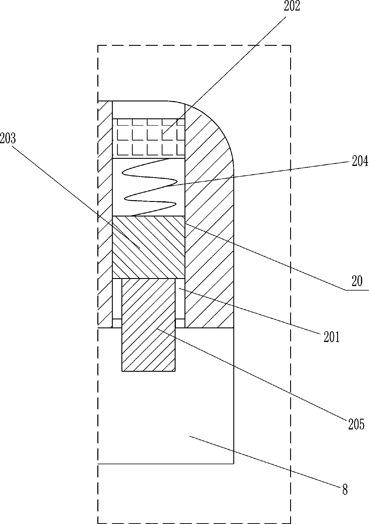
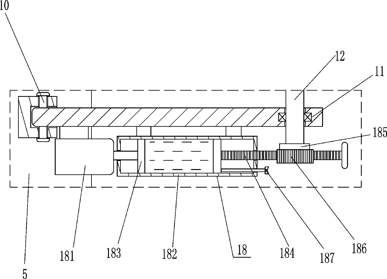
[0022] A tile cutting equipment such as Figure 1-2As shown, it includes a bottom plate 1, a baffle plate 2, a slide rail 3, a first slider 4, a mounting seat 5, a first cylinder 6, a moving deck 7, a fixed deck 8, a pulley 9, a rotating shaft 10, and a torsion spring 101 , swing bar 11, transmission rod 12, rubber roller 13, first motor 14, emery wheel 16 and driving mechanism 17, base plate 1 front and rear sides are connected with baffle plate 2, base plate 1 top left side is symmetrically provided with slide rail 3, slide rail 3 is provided with a first slider 4, the top of the first slider 4 on the left and right sides is connected with a mounting seat 5, and the front side of the top of the mounting seat 5 is provided with a first cylinder 6, and the telescopic rod of the first cylinder 6 is connected with a mobile card seat 7. There is a fixed deck 8 on the rear side of the top of the mounting base 5, and a plurality of pulleys 9 are provided on the inner bottom of the ...


PUM


Abstract

The invention relates to a cutting device, in particular to a ceramic tile cutting device. Therefore, the technical problem of the ceramic tile cutting device is that the ceramic tile cutting device which is high in working efficiency, capable of automatically feeding ceramic tiles, ensures the safety of operators, and cuts accurately is provided. According to the technical scheme, the ceramic tile cutting device comprises a bottom plate, baffles, a slide rail, first sliding blocks, mounting seats, first air cylinders, and a mobile clamping seat; the front side and the rear side of the bottomplate is connected with the baffles, the slide rail is symmetrically arranged on the left side of the top of the bottom plate, the first sliding blocks are arranged on the slide rail, the mounting seats are connected to the tops of the first sliding blocks on the left side and the right side, and the air first cylinders are arranged on the front sides of the tops of the mounting seats. According to the ceramic tile cutting device, the ceramic tiles can be fed through a feeding mechanism, an adjustment bolt can be screwed for moving left and right in a cylinder body, the distance of a piston moving to the right can be adjusted, the rotation ranges of a first gear and a rubber roller can also be adjusted, thus the feeding distance of ceramic tiles is adjusted, and feeding by using the deviceis more flexible.

Description

technical field [0001] The invention relates to a cutting device, in particular to a ceramic tile cutting device. Background technique [0002] During house decoration and construction, it is usually necessary to lay tiles. When laying tiles, it is necessary to cut the tiles. Sometimes it is necessary to cut a large number of large tiles into multiple small strips. The workload is relatively large. At present, the tiles are usually processed manually. Measure, and then draw the cutting reference line before cutting, which not only affects the cutting efficiency, but also needs to manually push the material every time it is cut. There is also the shortcoming of complicated and unsafe operation in the material. Contents of the invention [0003] In order to overcome the shortcomings of low efficiency, cumbersome manual feeding operation, low safety, and inaccurate feeding leading to cutting errors when manually measuring and cutting ceramic tiles, the technical problem of t...

Claims


Application Information

Patent Timeline
Patent Type & Authority Applications(China)
IPC IPC(8): B24B27/06B24B41/02B24B41/06B24B47/20
CPCB24B27/0683B24B41/02B24B41/06B24B47/20
Inventor 龙健
Owner 广东长海建设工程有限公司
Why Eureka
Try Eureka