A kind of tile cutting equipment
A cutting equipment, ceramic tile technology, applied in metal processing equipment, grinding/polishing equipment, manufacturing tools, etc., can solve the problems of cumbersome manual feeding operation, inaccurate feeding, low safety, etc., to improve cutting efficiency, Ease of operation and improved safety
- Summary
- Abstract
- Description
- Claims
- Application Information
AI Technical Summary
Problems solved by technology
Method used
Image
Examples
Embodiment 1
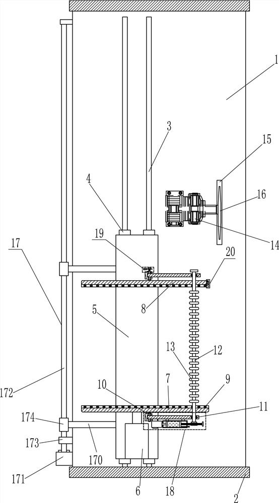
[0017] A tile cutting equipment such as figure 1 As shown, it includes a bottom plate 1, a baffle plate 2, a slide rail 3, a first slider 4, a mounting seat 5, a first cylinder 6, a moving deck 7, a fixed deck 8, a pulley 9, a rotating shaft 10, and a torsion spring 101 , swing bar 11, transmission rod 12, rubber roller 13, first motor 14, emery wheel 16 and driving mechanism 17, base plate 1 front and rear sides are connected with baffle plate 2, base plate 1 is connected with baffle plate 2 by the mode of welding connection, base plate 1 The left side of the top is symmetrically provided with a slide rail 3, the slide rail 3 is provided with a first slider 4, the top of the first slider 4 on the left and right sides is connected with a mounting seat 5, and the top front side of the mounting seat 5 is provided with a first cylinder 6 , the telescopic rod of the first cylinder 6 is connected with a movable deck 7, and the rear side of the top of the mounting base 5 is provided...
Embodiment 2
[0019] A tile cutting equipment such as figure 1 As shown, it includes a bottom plate 1, a baffle plate 2, a slide rail 3, a first slider 4, a mounting seat 5, a first cylinder 6, a moving deck 7, a fixed deck 8, a pulley 9, a rotating shaft 10, and a torsion spring 101 , swing bar 11, transmission rod 12, rubber roller 13, first motor 14, emery wheel 16 and driving mechanism 17, base plate 1 front and rear sides are connected with baffle plate 2, base plate 1 top left side is symmetrically provided with slide rail 3, slide rail 3 is provided with a first slider 4, the top of the first slider 4 on the left and right sides is connected with a mounting seat 5, and the front side of the top of the mounting seat 5 is provided with a first cylinder 6, and the telescopic rod of the first cylinder 6 is connected with a mobile card seat 7. There is a fixed deck 8 on the rear side of the top of the mounting base 5, and a plurality of pulleys 9 are provided on the inner bottom of the mo...
Embodiment 3
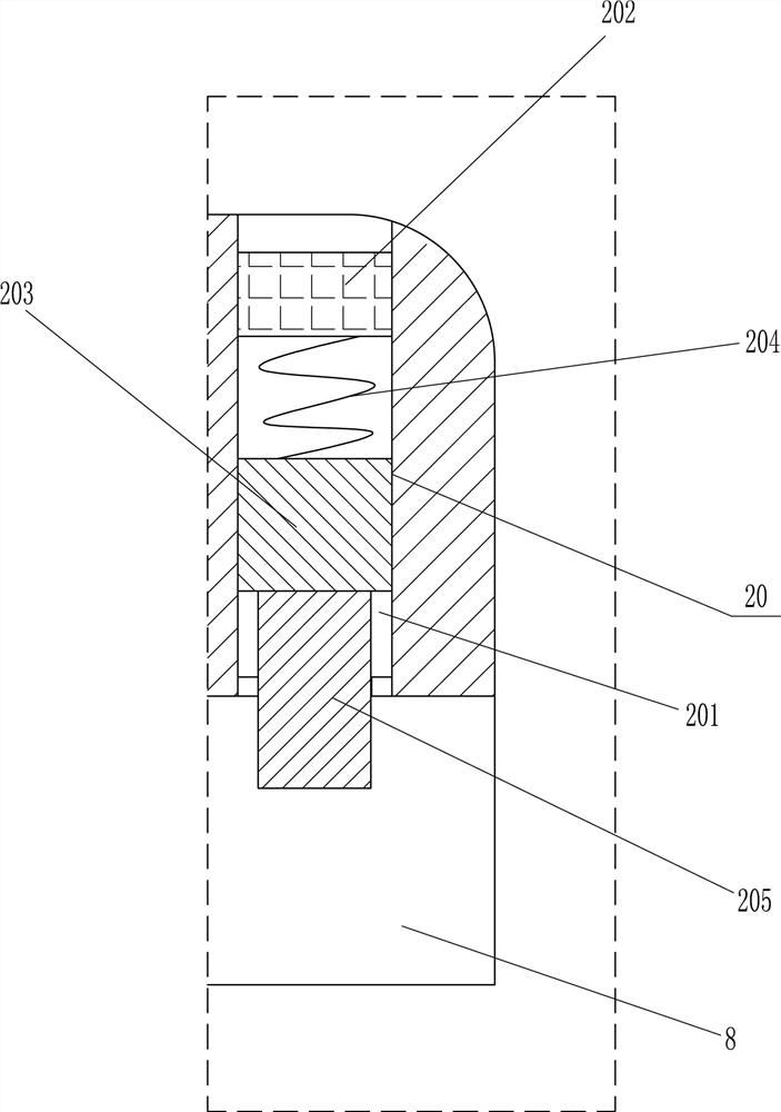
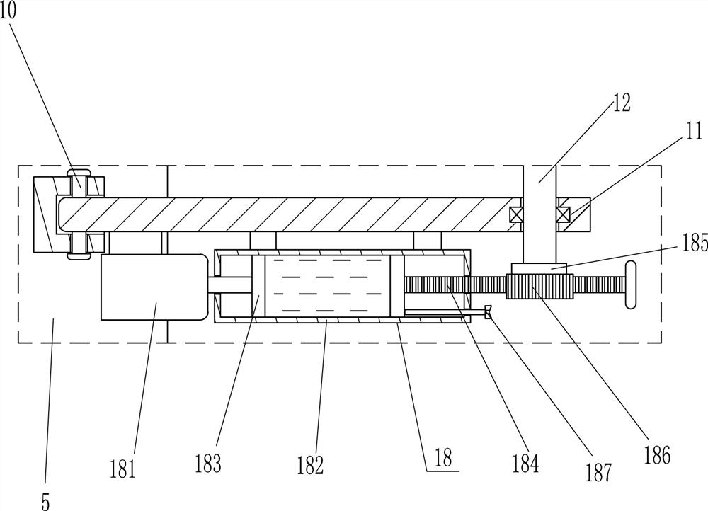
[0022] A tile cutting equipment such as Figure 1-2As shown, it includes a bottom plate 1, a baffle plate 2, a slide rail 3, a first slider 4, a mounting seat 5, a first cylinder 6, a moving deck 7, a fixed deck 8, a pulley 9, a rotating shaft 10, and a torsion spring 101 , swing bar 11, transmission rod 12, rubber roller 13, first motor 14, emery wheel 16 and driving mechanism 17, base plate 1 front and rear sides are connected with baffle plate 2, base plate 1 top left side is symmetrically provided with slide rail 3, slide rail 3 is provided with a first slider 4, the top of the first slider 4 on the left and right sides is connected with a mounting seat 5, and the front side of the top of the mounting seat 5 is provided with a first cylinder 6, and the telescopic rod of the first cylinder 6 is connected with a mobile card seat 7. There is a fixed deck 8 on the rear side of the top of the mounting base 5, and a plurality of pulleys 9 are provided on the inner bottom of the ...
PUM
 Abstract
Description
Claims
Application Information
 - R&D
- Intellectual Property
- Life Sciences
- Materials
- Tech Scout
- Unparalleled Data Quality
- Higher Quality Content
- 60% Fewer Hallucinations
Browse by: Latest US Patents, China's latest patents, Technical Efficacy Thesaurus, Application Domain, Technology Topic, Popular Technical Reports.
© 2025 PatSnap. All rights reserved.Legal|Privacy policy|Modern Slavery Act Transparency Statement|Sitemap|About US| Contact US: help@patsnap.com


