Transmission supporting mechanism for compact spinning carrier gear

A bridge gear and transmission support technology, which is applied to spinning machines, components with teeth, spinning machines with continuous winding, etc., can solve the problems of rising maintenance costs, shortened life, loss, etc., and achieve yarn quality Guarantee, reduce accuracy requirements, and reduce maintenance costs

Inactive Publication Date: 2020-04-14
江阴市华方新技术科研有限公司
View PDF0 Cites 0 Cited by
  • Summary
  • Abstract
  • Description
  • Claims
  • Application Information

AI Technical Summary

Problems solved by technology

[0006] 1. If you continue to use a section of 8-spindle front roller to drive a section of 8-spindle compact roller through a compact spinning bridge gear, then the load on the compact spinning bridge gear will increase a lot, and the compact spinning bridge gear will be easily damaged. , the service life is greatly shortened, the maintenance cost of the user is increased, the transmission is not stable, the yarn quality is deteriorated, and the risk and loss are caused to the end customer;
[0007] 2. The length of the small roller corresponding to the 8-spindle compact spinning is relatively long, and the shortcomings of the slender shaft parts are more fully exposed. It is easier to bend during the transmission process and cause vibration to deteriorate the quality of the yarn, causing risks and risks to end customers. loss;
[0008] 3. The length of the accumulating tube corresponding to 8 spindles is relatively long, and the accumulating tube is more likely to be bent and deformed to fail to meet the precision requirements, which will also deteriorate the quality of the yarn and cause risks and losses to end customers

Method used


Image

  • Transmission supporting mechanism for compact spinning carrier gear
  • Transmission supporting mechanism for compact spinning carrier gear
  • Transmission supporting mechanism for compact spinning carrier gear

Examples


Embodiment Construction

[0056] The present invention will be further described in detail below in conjunction with the accompanying drawings and embodiments.

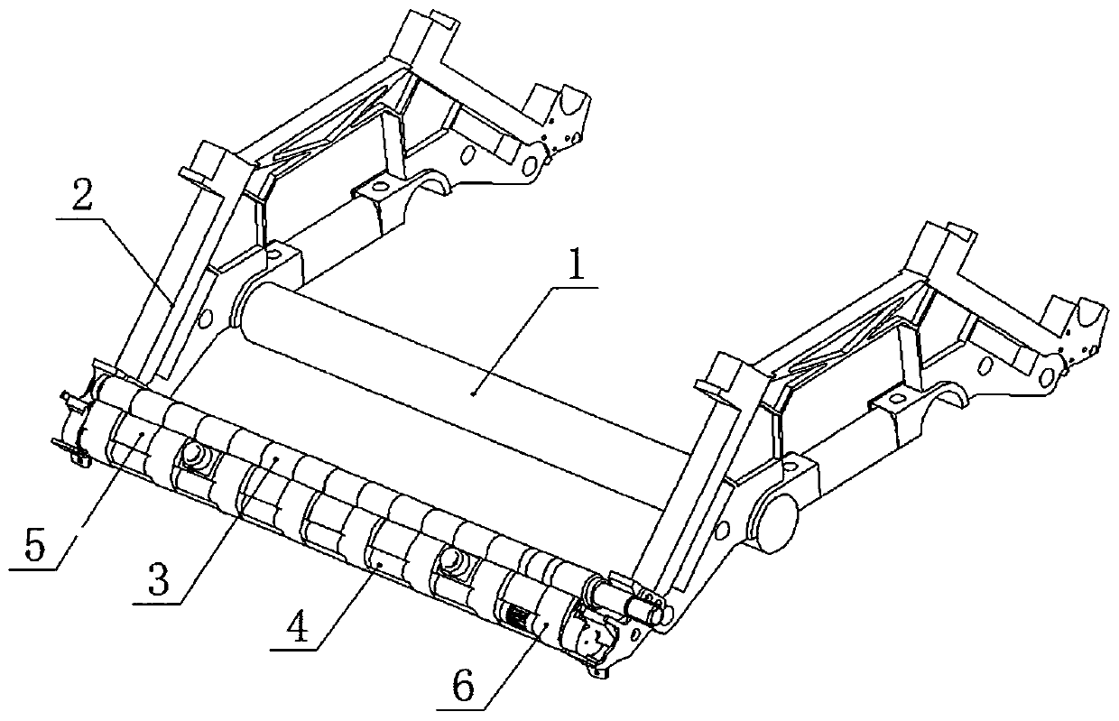
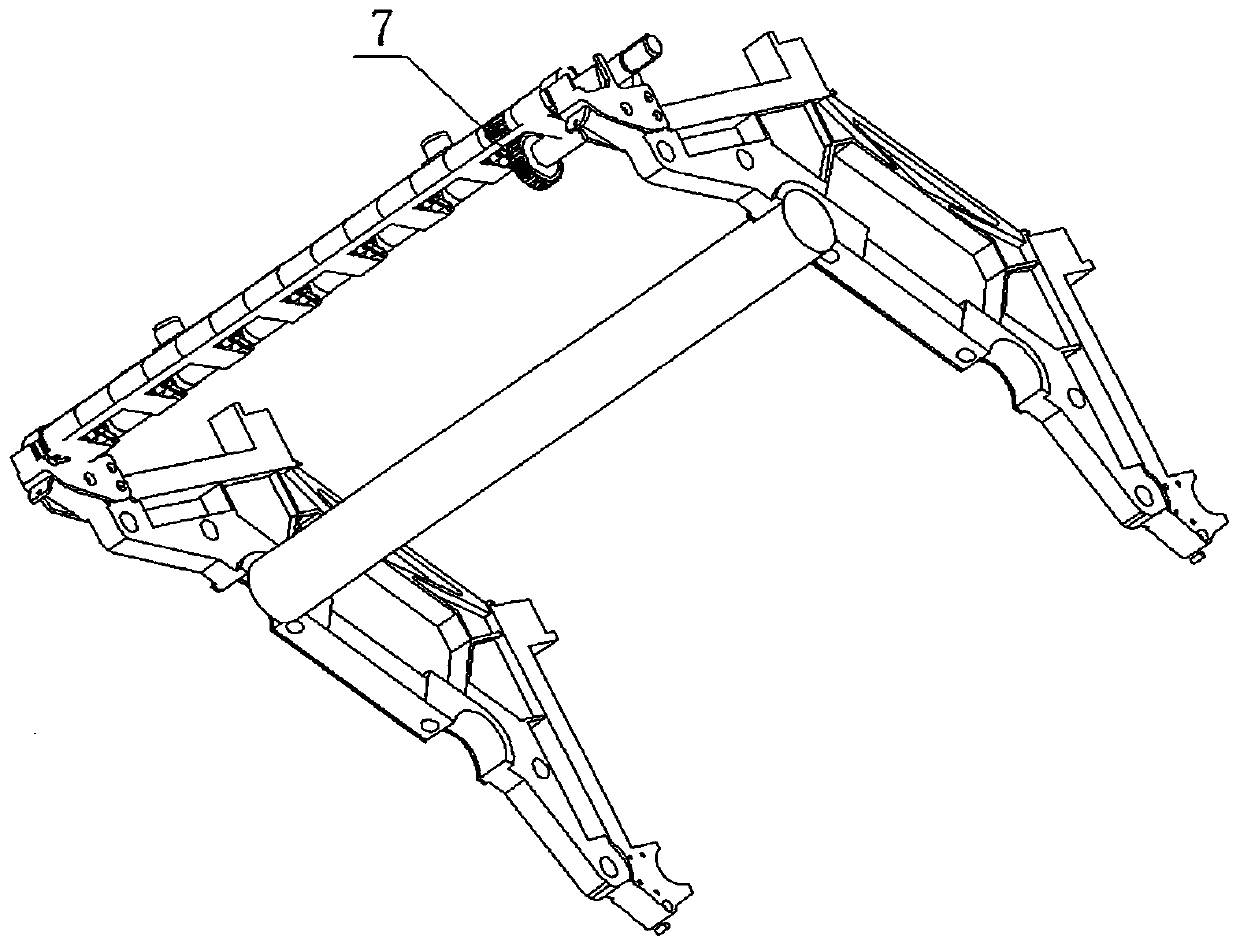
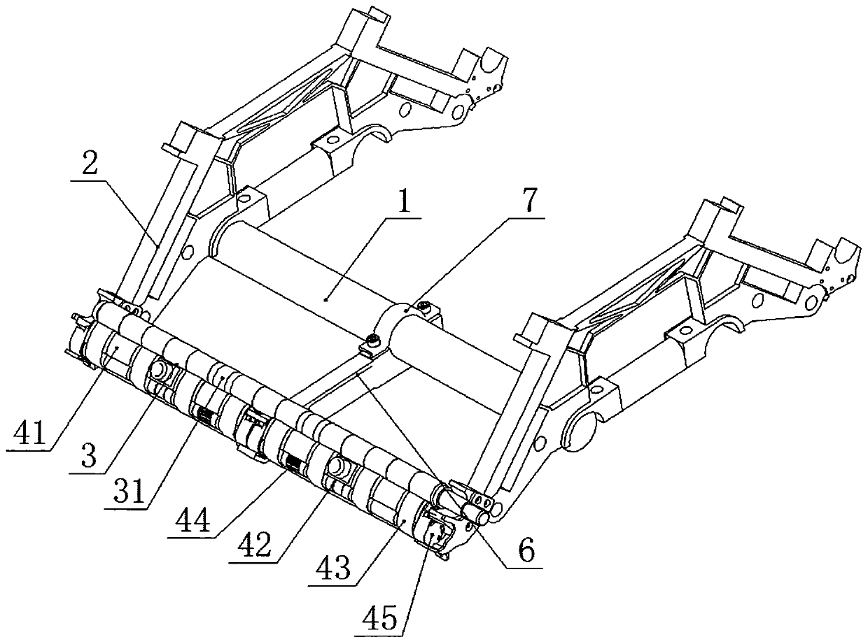
[0057] see Figure 3 to Figure 9 , the present invention relates to a transmission support mechanism for compact spinning bridge gears, which includes a circular machine beam 1, and the circular machine beam 1 is provided with two left and right roller seats 2, between the front parts of the left and right two roller seats 2 A front roller 3 is provided, and two accumulation mechanisms 4 on the left and right are arranged below the front roller 3, and a support arm 6 is arranged forward in the middle of the circular machine beam 1, and one end of the accumulation mechanism 4 rests on the front cantilever end of the support arm 6 , and the other end rests on the front part of the left or right roller seat 2;

[0058] Described gathering mechanism 4 comprises gathering pipe 41 and gathering small roller 42, is wound with a plurality of grid cir...


PUM


Abstract

The invention relates to a transmission supporting mechanism for a compact spinning carrier gear. The transmission supporting mechanism comprises a circular machine beam (1), wherein the circular machine beam (1) is provided with left and right roller seats (2); a front roller (3) is arranged between the front portions of the left and right roller seats (2); left and right gathering mechanisms (4)are arranged below the front roller (3); a support arm (6) is arranged in the middle of the circular machine beam (1) forwardly; one end of the gathering mechanism (4) is placed at the front end of the support arm (6), and the other end of the gathering mechanism (4) is arranged at the front part of the left roller seat or the right roller seat (2). The front roller drives left and right gathering small rollers through the left and right compact spinning carrier gears respectively, so that the load borne by the compact spinning carrier gear is greatly reduced, the compact spinning carrier gear is not prone to being damaged, the service life is greatly prolonged, the maintenance cost of a user is reduced, stable transmission is ensured, and the yarn quality is effectively guaranteed.

Description

technical field [0001] The invention relates to a transmission support mechanism of a compact spinning bridge gear, which belongs to the technical field of textile machinery. Background technique [0002] In the compact spinning frame, a compacting device is added in front of the front roller of the original spinning frame. This device includes compact spinning bridge gears, small compacting rollers, grid rings, compacting tubes and other parts. Driven by the transmission parts, the grid ring makes a rotary motion, and transports the drawn fiber forward, so that the fiber is gathered, twisted and spun into yarn. The parts of the transmission part are mainly the front roller, the compact spinning bridge gear, and the compact small roller. The transmission and support of the compact spinning bridge gear are closely related to the quality of the yarn. [0003] The transmission support mechanism of the existing compact spinning bridge gear is as follows: [0004] When the fron...

Claims


Application Information

Patent Timeline
Patent Type & Authority Applications(China)
IPC IPC(8): D01H1/22D01H5/72F16H55/17
CPCD01H1/22D01H5/72F16H55/17
Inventor 闫中旭汪仁晓陆荣海严朴顾垚
Owner 江阴市华方新技术科研有限公司
Why Eureka
Try Eureka