Vibrating bar positioning method in concrete vibrating process

A positioning method and vibrator technology, which is applied in the field of vibrator positioning during the concrete vibration process, can solve the problems of increasing the positioning error of the vibrator, affecting wireless signal transmission, and difficult to ensure the GPS positioning environment, etc. Effect of external environment, effect of improving positioning accuracy

Inactive Publication Date: 2020-04-14
上海中兴思秸通讯有限公司
View PDF10 Cites 5 Cited by
  • Summary
  • Abstract
  • Description
  • Claims
  • Application Information

AI Technical Summary

Problems solved by technology

The disadvantage of this method is that GPS positioning will be affected by factors such as personnel walking on the project site, steel mesh, templates, etc., resulting in inaccurate positioning
The disadvantage of this method is that the positioning accuracy of GPS is very high. In the actual construction environment, it is difficult to ensure the ideal GPS positioning environment, which makes it difficult for the GPS positioning accuracy to meet the application requirements.
The disadvantages of this method are: 1. A wireless signal transmitter needs to be installed on the artificial vibrator. When the head of the vibrator penetrates into the wall template or is completely immersed in the concrete, it will affect the wireless signal transmission and cause the positioning to be invalid; 2. , There are a large number of steel structures in the concrete pouring construction area, which greatly interferes with the reception of wireless signals, which will greatly increase the positioning error of the vibrator
The disadvantages of using the concrete vibrator positioning guide for positioning the vibrating rods are: 1. Each vibrating rod needs to be equipped with a concrete vibrating positioning guide, which is not flexible enough; 2. The front end of the concrete vibrating positioning guide The high-definition camera is highly likely to be damaged by the concrete during the vibration process; 3. The impact of the vibration caused by the vibrator on the high-definition camera image is difficult to eliminate

Method used


Image

  • Vibrating bar positioning method in concrete vibrating process
  • Vibrating bar positioning method in concrete vibrating process
  • Vibrating bar positioning method in concrete vibrating process

Examples


Embodiment Construction

[0026] The following will clearly and completely describe the technical solutions in the embodiments of the present invention with reference to the accompanying drawings in the embodiments of the present invention. Obviously, the described embodiments are only some, not all, embodiments of the present invention. Based on the embodiments of the present invention, all other embodiments obtained by persons of ordinary skill in the art without making creative efforts belong to the protection scope of the present invention.

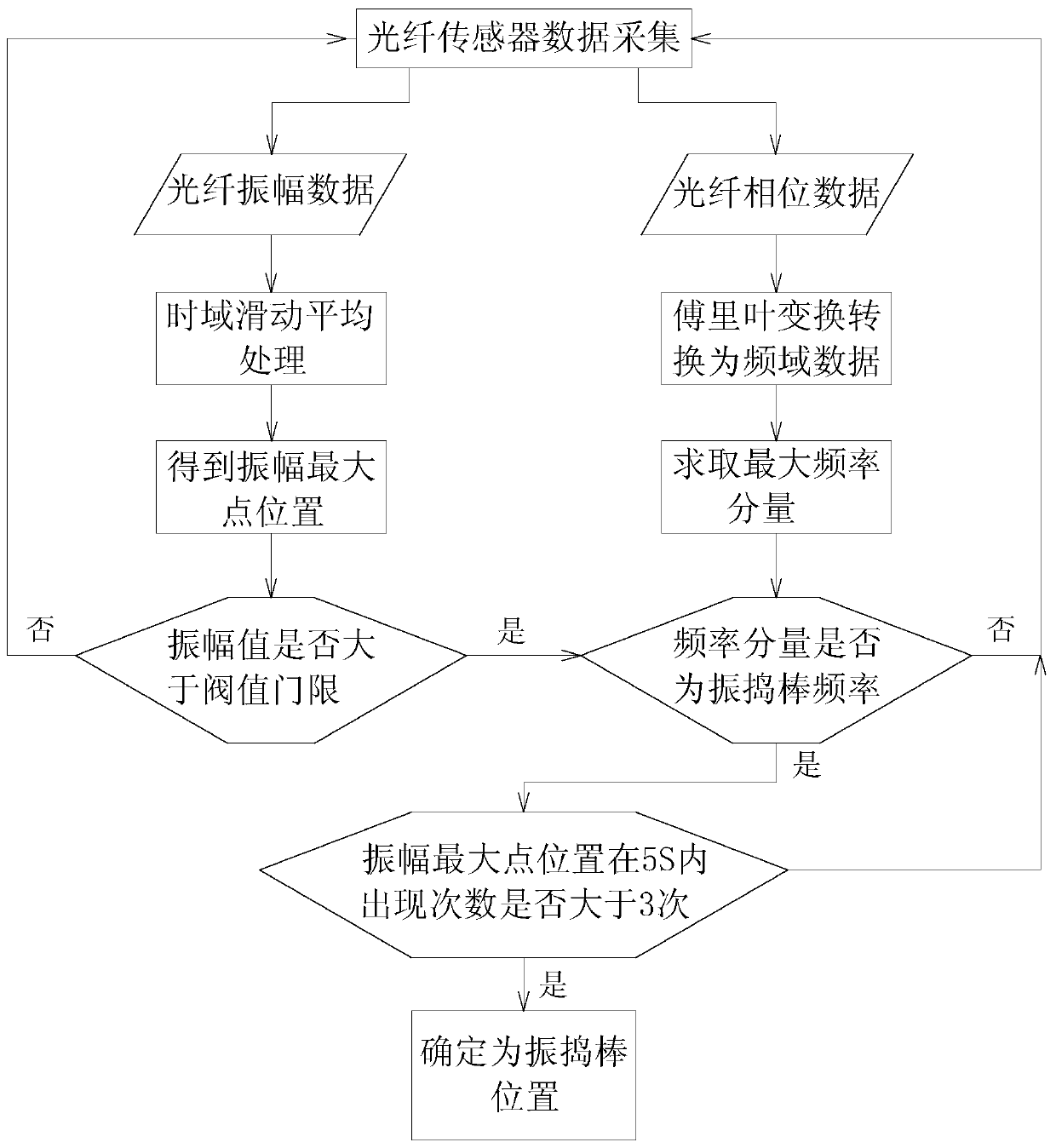
[0027] see Figure 1~5 , the present invention provides a technical solution: a method for positioning a vibrating rod in the concrete vibrating process, comprising the following steps:

[0028] S1. Lay sensing optical fibers in the vibration area, and multiple vibration monitoring points are distributed on the sensing optical fibers;

[0029] S2. Collect the amplitude and phase data of each monitoring point through the optical fiber sensing system, and send ...


PUM


Abstract

The invention discloses a vibrating bar positioning method in a concrete vibrating process. The method comprises the following steps that through an optical fiber sensor, amplitudes and phase data ofeach monitoring point are collected, and the obtained amplitudes and the phase data are sent to a server; the server receives the amplitude data, the amplitude data of the monitoring points are subjected to time domain sliding average treatment on a time domain, and the amplitude data with the large fluctuation can be removed; after the server receives the phase data, the phase data are subjectedto transform treatment, and monitoring point frequency domain data are obtained; the position of the maximum amplitude point and the maximum amplitude value are obtained; the amplitude maximum frequency of the monitoring point corresponding to the maximum amplitude point is matched with the vibrating bar frequency, the position, the amplitude, the time and other information of the monitoring points are written into a database; and it is ensured that the position where the monitoring points are located is the vibrating bar actual position. Through the method, the position of the vibrating bar is positioned, the influence of the construction site external environment can be effectively removed, and the vibrating bar positioning precision can be improved.

Description

technical field [0001] The invention relates to the technical field of optical fiber sensing vibration detection, in particular to a vibrating rod positioning method in the concrete vibrating process. Background technique [0002] During the concrete pouring process, in order to ensure the strength of the concrete, vibration work is required to ensure the compactness of the concrete. During the on-site construction process, the concrete vibration completely relies on the experience of the construction personnel and the supervision of the supervisors. There is no effective monitoring method to monitor the vibration process. Therefore, during the vibration operation, due to irregular operations, vibration leakage, Phenomena such as under-vibration and over-vibration require follow-up remediation, resulting in delays in project progress and waste of resources. [0003] By positioning the vibrating rod through the optical fiber, the vibrating condition of the vibrating rod can ...

Claims


Application Information

Patent Timeline
Patent Type & Authority Applications(China)
IPC IPC(8): E04G21/08
CPCE04G21/08
Inventor 刘博孙畅江平张亮姜云伍伟
Owner 上海中兴思秸通讯有限公司
Why Eureka
Try Eureka