Continuous feeding and discharging quick dewatering and drying device for sand fine stones for building construction

A drying device and building construction technology, which is applied to heating devices, drying solid materials, drying chambers/containers, etc., can solve the problems of slow drying measures, large drying boxes, slow conveyor belts, etc., to ensure dehydration efficiency, The effect of preventing energy waste and improving the degree of automation

Active Publication Date: 2020-04-14
浙江腾升建设有限公司
View PDF11 Cites 1 Cited by
  • Summary
  • Abstract
  • Description
  • Claims
  • Application Information

AI Technical Summary

Problems solved by technology

[0004] In the prior art, sand and gravel are usually dried by means of drying. The sand and gravel are put into the drying box for a long time drying operation. Such a dehydration device consumes a lot of energy because the high temperature in the drying box must be maintained for a long time. Moreover, moisture evaporates and accumulates in the drying box, and the air in the drying box needs to be replaced continuously for dehumidification. When the

Method used


Image

  • Continuous feeding and discharging quick dewatering and drying device for sand fine stones for building construction
  • Continuous feeding and discharging quick dewatering and drying device for sand fine stones for building construction
  • Continuous feeding and discharging quick dewatering and drying device for sand fine stones for building construction

Examples


Example Embodiment

[0031] The technical solutions in the embodiments of the present invention will be clearly and completely described below in conjunction with the accompanying drawings in the embodiments of the present invention. Obviously, the described embodiments are only a part of the embodiments of the present invention, rather than all the embodiments. Based on the embodiments of the present invention, all other embodiments obtained by those of ordinary skill in the art without creative work shall fall within the protection scope of the present invention.

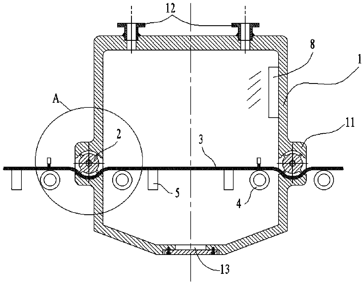
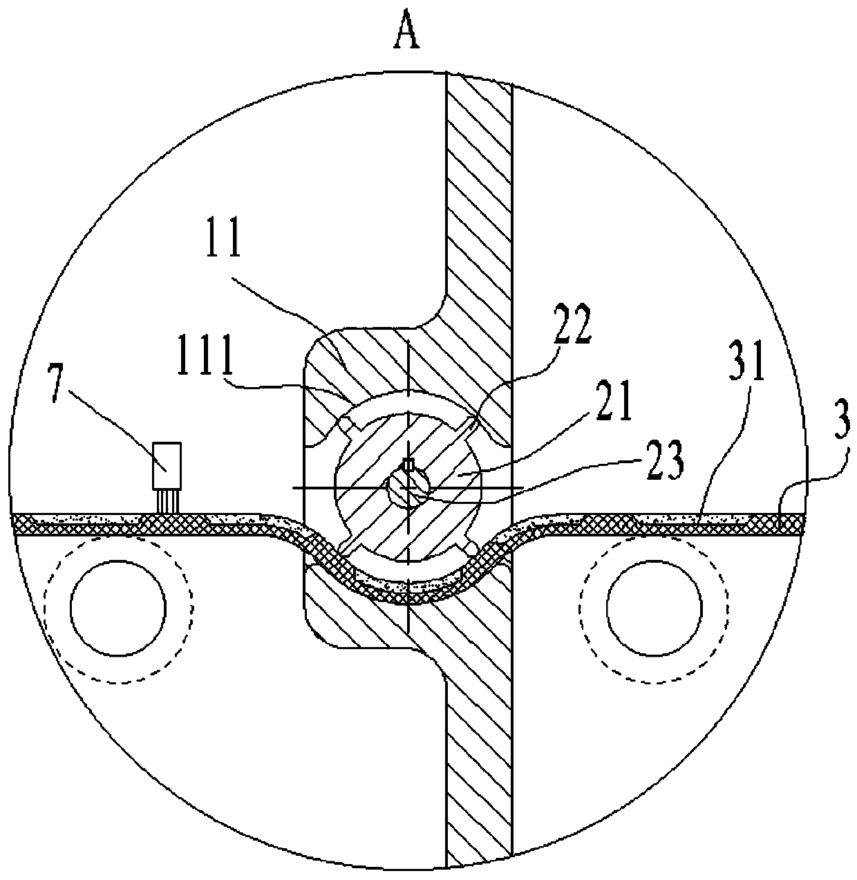
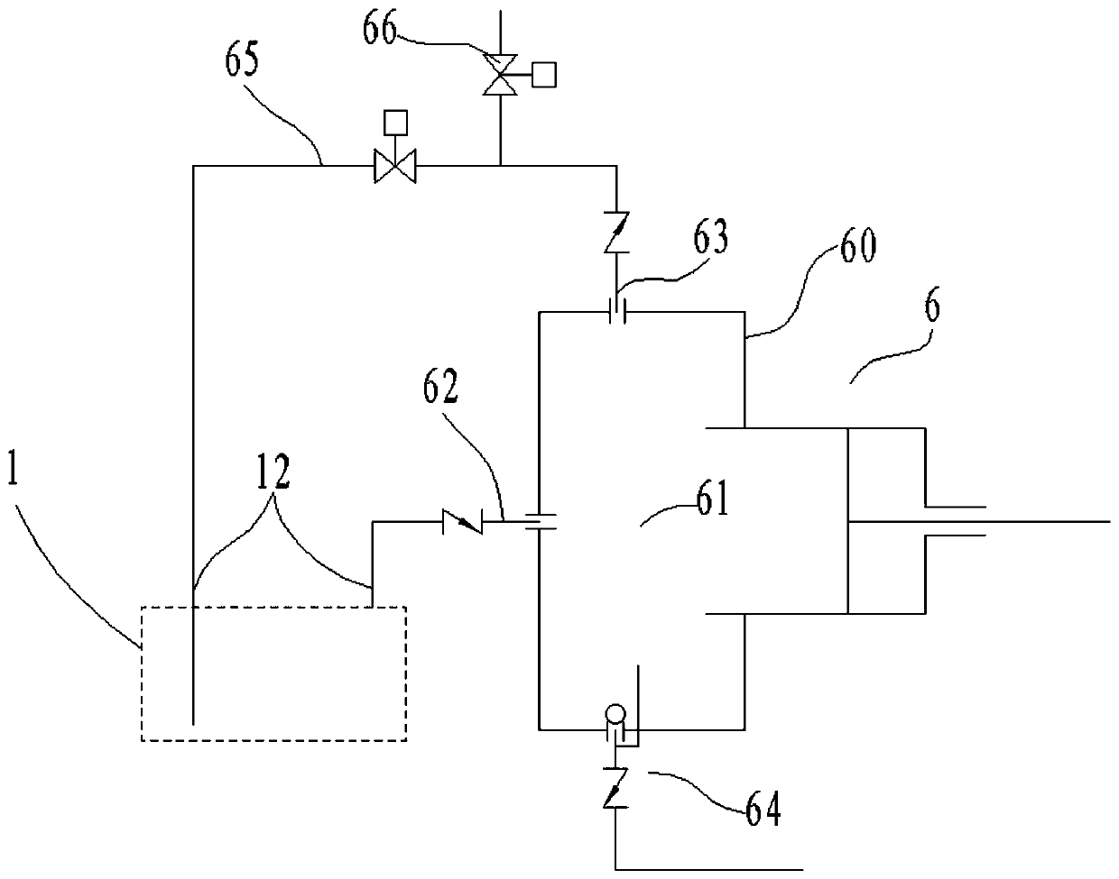
[0032] Such as figure 1 , 3 As shown, the continuous feeding and discharging rapid dehydration and drying device of sand and fine stone for construction includes a dehydration tank 1, a sealing wheel 2, a conveyor belt 3 and a vacuum pump 6. The dehydration tank 1 includes a tank body and two sets on the wall of the tank body. The sealing wheel installation platform 11 and the circulation interface 12, the sealing wheel installation platf...


PUM


Abstract

The invention discloses a continuous feeding and discharging quick dewatering and drying device for sand fine stones for building construction. The device comprises a dehydration tank, sealing wheels,a conveying belt and a vacuum pump. The dehydration tank comprises a tank body, two sealing wheel mounting tables and a circulating interface, wherein the two sealing wheel mounting tables and the circulating interface are arranged on the wall surface of the tank body, and sealing wheels are mounted in the sealing wheel mounting tables; the conveying belt passes through the two sealing wheel mounting tables and is extruded by the sealing wheels in the sealing wheel mounting tables; and the vacuum pump is connected with the dehydration tank. A heater is arranged in the dehydration tank; the vacuum pump comprises a pump body, an inlet valve, an exhaust valve, a drain valve and an exhaust pipe. A vacuum cavity is connected with the dehydration tank through pipelines, and the inlet valve andthe exhaust valve are arranged on the two pipelines; the exhaust pipe behind the exhaust valve is provided with two branches which are connected to the dehydration tank and the external atmosphere respectively; the two branches are respectively provided with an on-off valve; a drainage pipeline leading to the outside is arranged at the bottom of the vacuum cavity, and the drain valve is arranged on the drainage pipeline.

Description

technical field [0001] The invention relates to the field of drying devices, in particular to a rapid dehydration and drying device for continuously feeding and discharging sand and fine stones for building construction. Background technique [0002] Construction sand and gravel are finely crushed sand and fine stones with a diameter of a few tenths to several millimeters. During production, natural stones and sand and gravel are mechanically crushed and other steps are taken. The finished sand and gravel are put into the market as construction materials for sale. [0003] During the production or stacking of sand and gravel, some water may be mixed in, and the water increases the weight of the sand and gravel. If the sand and gravel are directly transported, the transportation cost will be higher. Therefore, the tailing of the sand and gravel production process is often dehydration. drying part. [0004] In the prior art, sand and gravel are usually dried by means of dryin...

Claims


Application Information

Patent Timeline
IPC IPC(8): F26B5/04F26B17/04F26B23/00F26B25/02F26B25/12
CPCF26B5/04F26B17/04F26B23/00F26B25/02F26B25/12
Inventor 李杰
Owner 浙江腾升建设有限公司
Why Eureka
Try Eureka