
High-strength parallel pulse magnet device

A pulse magnet, high-strength technology, applied in the electromagnetic field, can solve the problems of increasing the capacity of the discharge capacitor, increasing the cost, and insufficient magnetic field strength

Inactive Publication Date: 2020-04-14
HUAZHONG UNIV OF SCI & TECH
View PDF4 Cites 5 Cited by
  • Summary
  • Abstract
  • Description
  • Claims
  • Application Information

AI Technical Summary

Problems solved by technology

[0004] (1) The pulsed magnets at the present stage are usually wound in the form of a helical tube with a single wire. In order to obtain higher field strength, the number of turns or layers of the coil is often increased, but at the same time the impedance of the magnet is also significantly increased, and the peak value of the magnetic field of the magnet cannot be reached. The expected strength, and the increase of loop damping will make the pulse width of the discharge current significantly wider, which is not conducive to the generation of eddy current effect in the electromagnetic forming process, and the electromagnetic energy conversion rate will be greatly affected, and the insufficient magnetic field strength will seriously limit the observation of physical properties in scientific experiments range
In order to solve such problems, the current method is usually to increase the capacity of the discharge capacitor, but this will significantly increase the cost

Method used


Image

  • High-strength parallel pulse magnet device
  • High-strength parallel pulse magnet device
  • High-strength parallel pulse magnet device

Examples


Embodiment Construction

[0025] In order to make the object, technical solution and advantages of the present invention clearer, the present invention will be further described in detail below in conjunction with the accompanying drawings and embodiments. It should be understood that the specific embodiments described here are only used to explain the present invention, not to limit the present invention.

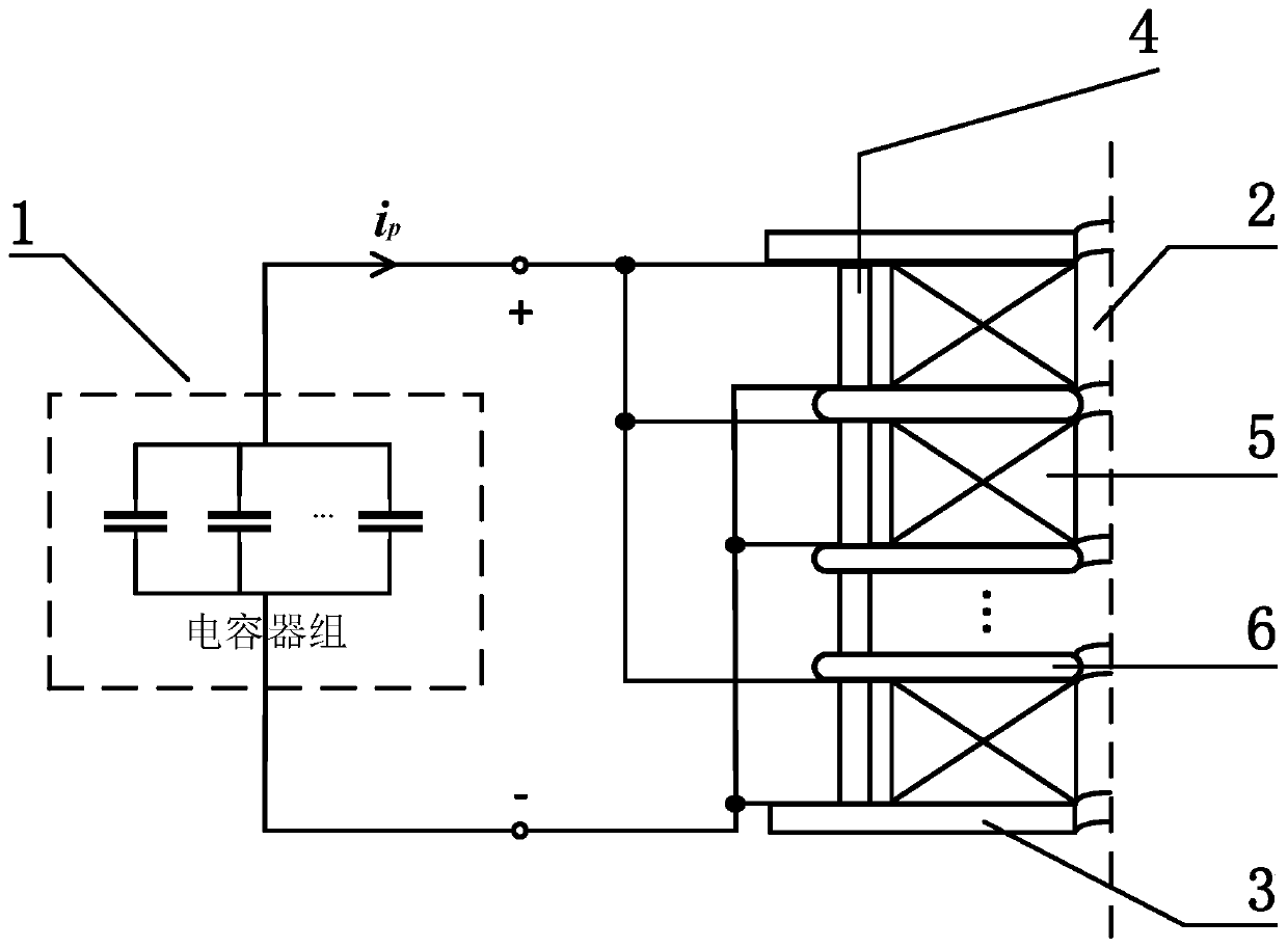
[0026] figure 1 The structure of the high-intensity parallel pulse magnet device provided by the embodiment of the present invention is shown. For the convenience of description, only the parts related to the embodiment of the present invention are shown, and the details are as follows:

[0027] The invention provides a high-strength, high-efficiency parallel-connected pulse magnet device, which reduces the magnet impedance by using the parallel connection of magnet coils, generates a larger pulse current under a certain discharge voltage, and improves the efficiency of electromagnetic energy. con...


PUM


Abstract

The invention belongs to the technical field of electromagnetism, and particularly discloses a high-strength parallel pulse magnet device which comprises a power supply module and a pulse magnet module. The pulse magnet module comprises a magnet unit, a supporting rod and two first reinforcing plates arranged at two ends of the supporting rod respectively. The magnet unit is arranged between the two first reinforcing plates and is electrically connected with the power supply module, and the supporting rod is arranged on a periphery of the magnet unit and is used for limiting and fixing plate layers with different heights so that the plate layers are coaxial and do not generate relative displacement. The magnet unit is composed of n groups of magnet coils connected in parallel. During work,an impedance of the pulse magnet module is reduced to 1 / n of the original impedance by the magnet coils connected in parallel under a condition that the number of turns of the coils is the same, a pulse current with higher intensity is obtained, and a magnetic field with higher intensity is induced. The magnet unit is axially separated through a second reinforcing plate, an axial stress of the magnet unit is shared, and mechanical structural strength of the whole pulse magnet device is improved.

Description

technical field [0001] The invention belongs to the field of electromagnetic technology, and more specifically relates to a high-intensity parallel pulse magnet device. Background technique [0002] With the continuous development of strong magnetic field technology, engineering and scientific research based on this extreme environment have made great progress, but there is still a lot of room for development. For example, in the field of electromagnetic forming, increasing the magnetic field strength can obtain greater electromagnetic force, thereby improving the forming efficiency of materials. In addition, in scientific experiments such as strong magnetic field X-ray diffraction, research on spallation neutron sources, and observation of physical properties of condensed matter, The increase in magnetic field strength can greatly broaden the scope of physical property research in extreme environments, and provides the possibility for inducing substances to exhibit various ...

Claims


Application Information

Patent Timeline
IPC IPC(8): H01F7/20
CPCH01F7/202
Inventor 韩小涛刘沁莹吴泽霖谌祺曹全梁李亮
Owner HUAZHONG UNIV OF SCI & TECH
Learn More