Solar power generation system

A power generation system and solar energy technology, which is applied in the field of solar power generation, can solve the problems of small portable power generation system, inconvenient installation of solar power generation system, small solar power generation system, etc., so as to improve power generation effect, increase absorption effect, and increase power generation Effect

Inactive Publication Date: 2020-04-14
何士卓
View PDF0 Cites 1 Cited by
  • Summary
  • Abstract
  • Description
  • Claims
  • Application Information

AI Technical Summary

Problems solved by technology

[0002] At present, known medium-sized and large-scale solar power generation systems are fixed, and are usually installed on roofs, wall surfaces, barren hills, barren slopes, deserted beaches, etc. There are also some portable solar power systems, but almost all portable solar power systems are It is very small, the power supply is limited, and its promotion and application are limited
[0003] Solar power generation has been widely used in Beichuan, Dujiangyan and other disaster-stricken areas during the "5.12" earthquake relief process, and provided power services for the disaster relief and disease prevention emergency team of the Ministry of Health, Sichuan Disease Control, Guiyang Fire Protection and other rescue units, but in the application During the process, it was found that the installation of a large-scale solar power generation system is inconvenient and takes a lot of time, while the small portable power generation system cannot meet the needs of various power consumption due to its small power

Method used


Image

  • Solar power generation system
  • Solar power generation system
  • Solar power generation system

Examples


Embodiment Construction

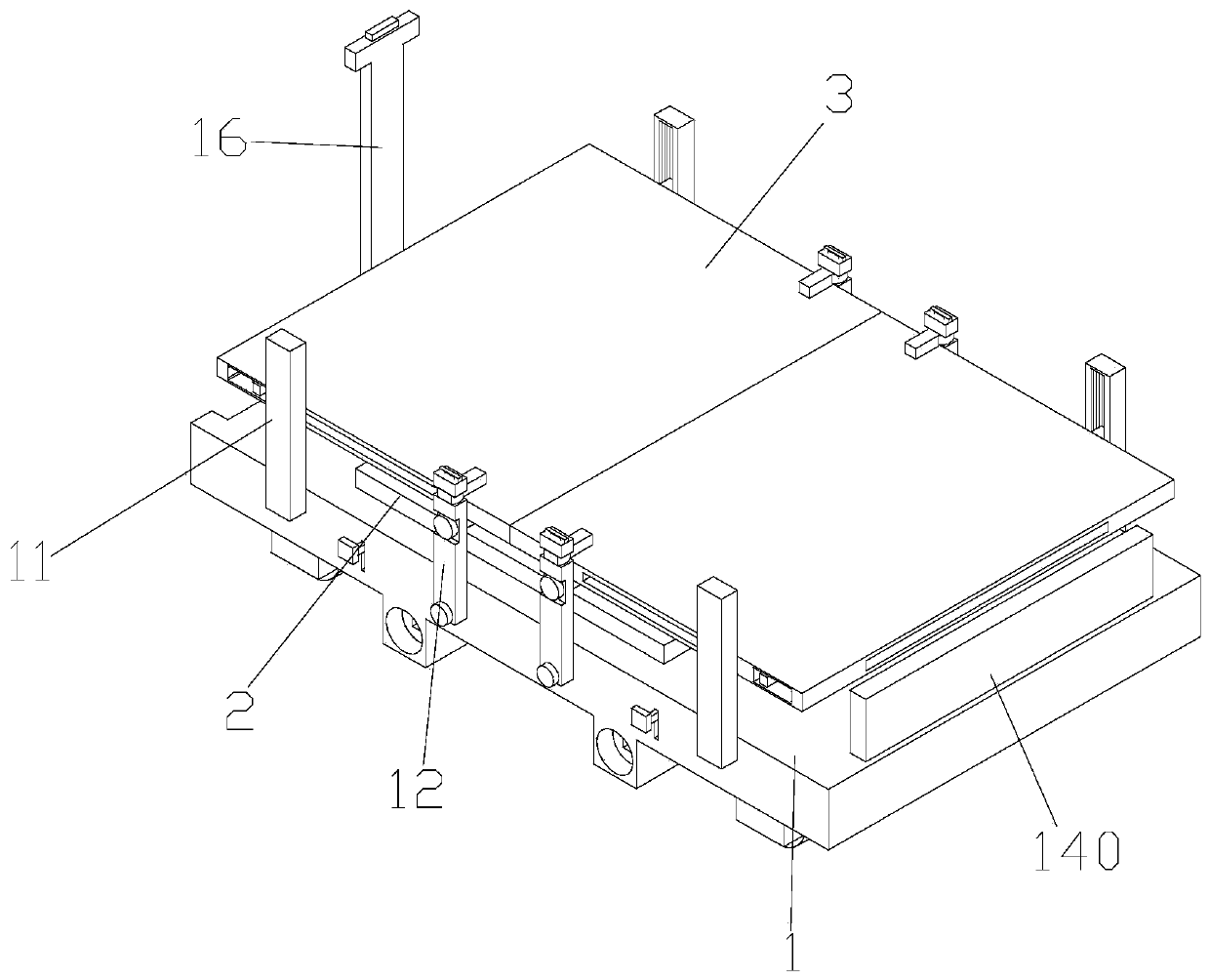
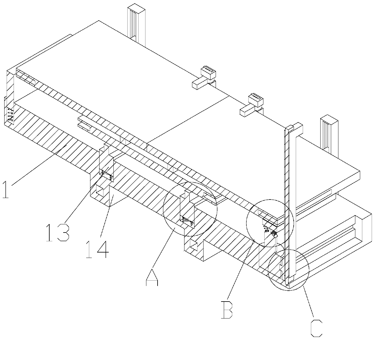
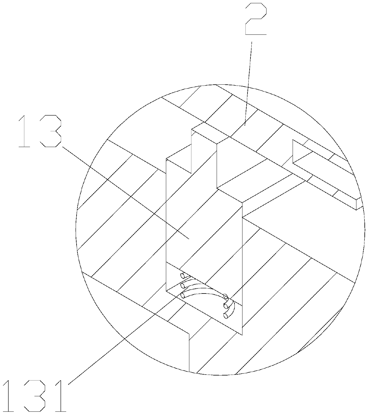
[0033] Such as Figure 1-17 As shown, a solar power generation system includes a base plate 1, a first photovoltaic panel 2 and a second photovoltaic panel 3 arranged on the base plate 1, and the second photovoltaic panels are two groups, which are respectively arranged on the top of the base plate On both sides, the bottom of the base plate 1 is provided with a first connecting block, and the first connecting block is provided with a universal wheel 110. The universal wheel is a universal wheel with brakes on the market, so that after the base plate moves, Fix the bottom plate at a designated position; the bottom plate 1 is provided with a first movable slot, and a first support block 13 is arranged in the first movable slot, and the first photovoltaic panel 2 is movably connected to the first support On the block 13, a third support spring 131 is provided at the bottom of the first support block, under the action of the third support spring, the first photovoltaic panel alwa...


PUM


Abstract

The invention discloses a solar power generation system. The system comprises a bottom plate, a first photovoltaic panel and a second photovoltaic panel, the first photovoltaic panel and the second photovoltaic panel are arranged on the bottom plate, a first connecting block is arranged at the bottom of the bottom plate, universal wheels are arranged on the first connecting block, a first movablegroove is formed in the bottom plate, a first supporting block is arranged in the first movable groove, and the first photovoltaic panel is movably connected to the first supporting block; a first connecting rod is arranged on the side wall of the bottom plate, a first sliding groove is formed in the first connecting rod, a first sliding block is arranged in the first sliding groove, and the second photovoltaic panel is rotatably connected to the first sliding block; an air cylinder matched with the second photovoltaic panel is arranged on the bottom plate; under the mutual cooperation of thefirst photovoltaic panel and the second photovoltaic panel, a photovoltaic panel area with a large area is formed on the bottom plate, the sunlight absorption effect of the solar power generation system is improved, the power generation capacity of the power generation system is improved, and various different power utilization requirements are met.

Description

technical field [0001] The invention belongs to the technical field of solar power generation, and in particular relates to a solar power generation system. Background technique [0002] At present, the known medium-sized and large-scale solar power generation systems are fixed, and are usually installed on roofs, wall surfaces, barren hills, barren slopes, deserted beaches, etc. There are also some portable solar power systems, but almost all portable solar power systems are It is very small, and the power supply is limited, which limits its popularization and application. [0003] Solar power generation has been widely used in Beichuan, Dujiangyan and other disaster areas during the "5.12" earthquake relief process, and provided power services for the disaster relief and disease prevention emergency team of the Ministry of Health, Sichuan Disease Control, Guiyang Fire and other rescue units, but in the application During the process, it was found that the installation of ...

Claims


Application Information

Patent Timeline
IPC IPC(8): H02S10/40H02S20/30
CPCH02S10/40H02S20/30Y02E10/50
Inventor 何士卓
Owner 何士卓
Why Eureka
Try Eureka