An automatic sealing feeding and discharging device for a coating machine

An automatic sealing, feeding and discharging technology, which is applied in the direction of making medicines into special physical or ingestible devices, coatings, confectionery industry, etc., can solve the problems of affecting production efficiency, high work intensity, low efficiency, etc., to achieve It is convenient for feeding operation, realizes the effect of airtight discharge and reduces environmental pollution

Active Publication Date: 2022-02-15
BEIJING UNIV OF TECH
View PDF9 Cites 0 Cited by
  • Summary
  • Abstract
  • Description
  • Claims
  • Application Information

AI Technical Summary

Problems solved by technology

In the process of food and pharmaceutical production, especially tablets and candies, coating work is required, and the feeding and discharging of coating machines are all done manually, with a low degree of automation, considerable work intensity, and a long time-consuming process. Seriously affect production efficiency
The feeding of the coating machine generally adopts the method of manual dumping, or uses a feeding funnel to directly pour the raw material particles in the material barrel into the coating machine or the funnel; most of the discharging methods of the coating machine are manually installed inside and outside the discharge device , this feeding and discharging method has low efficiency and high labor costs. During the feeding and discharging process, the particles will be exposed outside the coating machine cylinder, which may not reach the hygienic level.
Aiming at the problems of low feeding and discharging efficiency and heavy workload of the coating machine, the invention designs a new feeding and discharging device of the coating machine

Method used


Image

  • An automatic sealing feeding and discharging device for a coating machine
  • An automatic sealing feeding and discharging device for a coating machine
  • An automatic sealing feeding and discharging device for a coating machine

Examples


Embodiment Construction

[0025] In order to make the above objects, features, and advantages of the present invention, the specific embodiments of the present invention will be described in detail below with reference to the accompanying drawings.

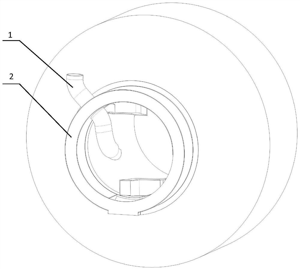
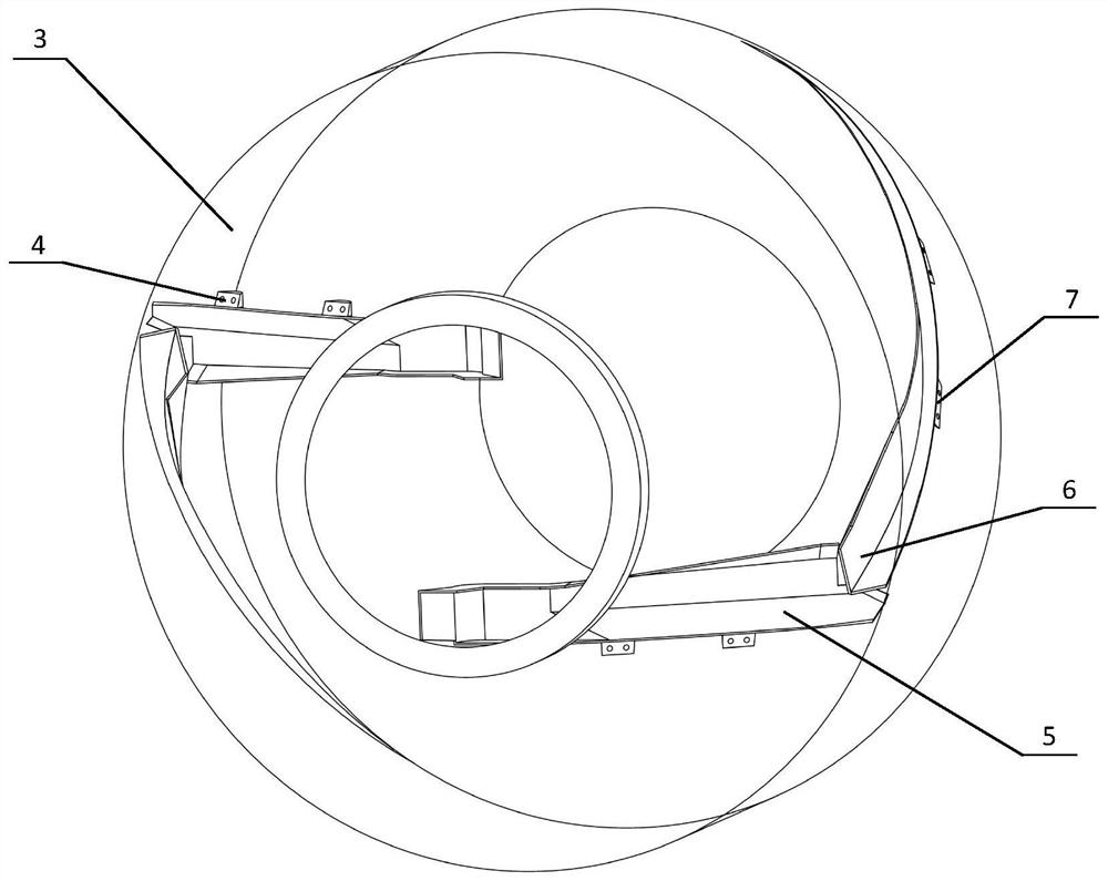
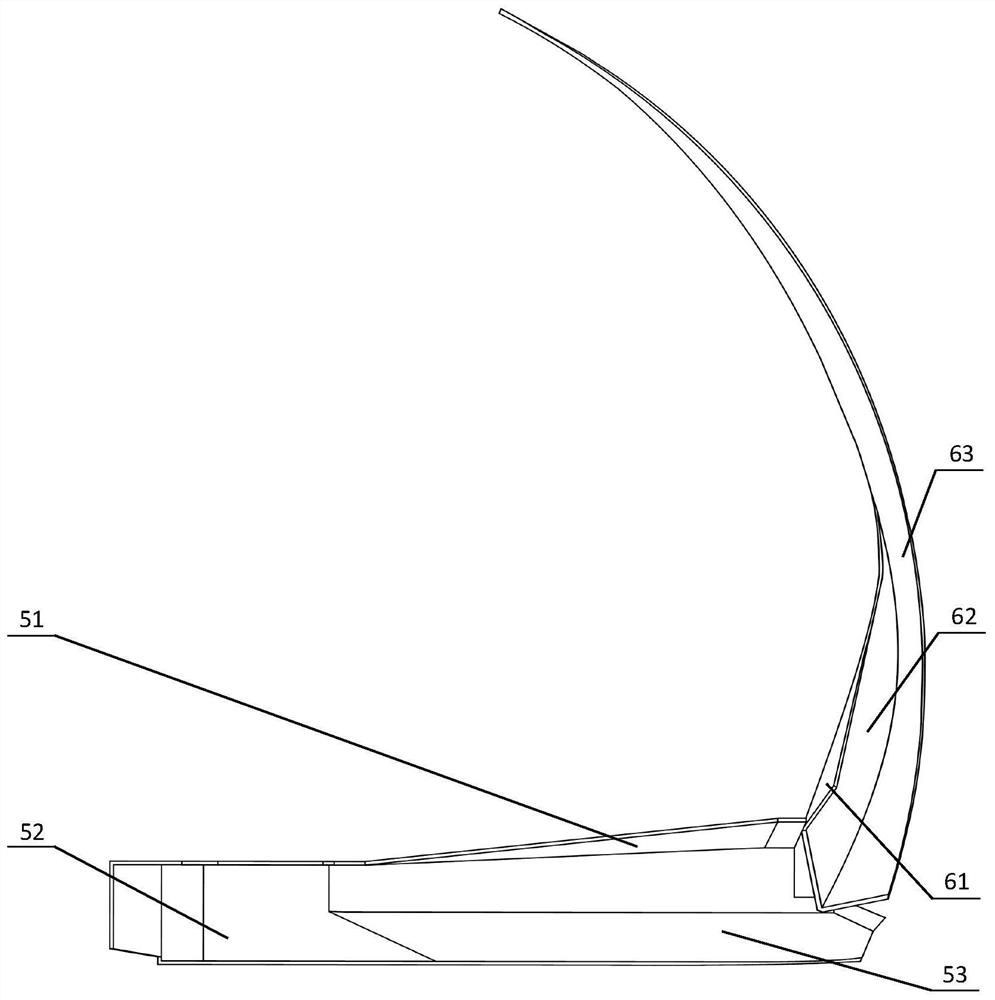
[0026] See Figure 1-4 The coating machine is automatically sealed with the overall structure of the entry and exit device, including the coating cylinder, the large door extension section, the projected blade and the rear projection blade. The front end of the coating cylinder is in the center of which is fully enclosed, the front and rear portion is a tapered bucket, the middle is a cylindrical bucket, the front conical bucket inside the tapered bucket through the screw installation Isolated blade mount, the interior of the central cylindrical bucket is installed after the screw is mounted, and the mount is mounted in the interior of the coating cylinder; the front feed blade welded to the front feed blade mounting seat; The rear proof blade is welded to the ...


PUM


Abstract

The invention discloses an automatic airtight material inlet and outlet device for a coating machine, which includes a coating tank and an extended section of a door body. It is a cylindrical barrel, the inside of the front conical barrel is installed with the front discharge blade mounting seat through screws, and the inside of the middle cylindrical barrel is installed with the rear discharge blade mounting seat through screws; the front discharge blade is welded on the front On the mounting seat of the discharge blade; the rear discharge blade is welded on the mounting seat of the rear discharge blade; the door body extension is installed outside the inlet and outlet of the coating tank; the feeding pipe is installed on the upper left of the door body extension and runs through the door body extension The segment outer ring and the gate body lengthen the segment inner ring. The invention can quickly and conveniently feed the coating machine, and can realize automatic discharge by using the reverse rotation of the coating machine, without opening and closing the door of the coating machine, reducing environmental pollution in production, ensuring the efficiency and quality of feeding and discharging materials, and basically realizing production automation.

Description

Technical field [0001] The present invention relates to a food and a pharmaceutical production line apparatus, in particular, relates to a coil machine automatic sealed feed apparatus. Background technique [0002] The use of food and pharmaceutical production lines at home and abroad is quite common, and automation of each production step has been basically achieved, but it is still inadequate. In the process of food and drug production, especially tablets and candies, we need to work in coating, in which the coating machine's entry and exit is completed, the degree of automation is not high, the working strength is quite large, the time is long, Severe affecting production efficiency. The coating machine is generally artificially dumped, or the use of the above funnel, pour the raw material particles in the bucket directly into the coating machine or funnel; most of the coating machine is used to install the internal and external feeder by manual installation. This type of impo...

Claims


Application Information

Patent Timeline
Patent Type & Authority Patents(China)
IPC IPC(8): A61J3/00A23G3/54
CPCA61J3/005A23G3/54
Inventor 高国华杨子昭刘本东
Owner BEIJING UNIV OF TECH
Why Eureka
Try Eureka