
Beauty mask structure

A cosmetic mask, face mask technology, applied in the directions of eye mask, radiation therapy, eye surgery, etc., can solve problems such as the inability of cosmetic mask to do other things, cataract, eye light damage, etc.

Pending Publication Date: 2020-04-17
XIAMEN JOYA TECH
View PDF0 Cites 4 Cited by
  • Summary
  • Abstract
  • Description
  • Claims
  • Application Information

AI Technical Summary

Problems solved by technology

However, when the light of light sources such as LEDs with different wavelengths is used for facial treatment or beauty treatment, it is very easy to cause damage to the eyes; for example, direct irradiation of a certain intensity of infrared rays on the eyes can cause cataracts or thermal damage to the retina; exposure to blue light for a certain period of time, It is easy to cause optical damage to the eyes, accelerate the oxidation of cells in the macular area, generate a large number of free radicals, and cause problems such as cataracts and macular degeneration
[0003] The existing beauty mask is worn on the face of the human body and irradiates the face with light generated by the LED lamp, so as to perform beauty treatment on the face of the human body; Damaged by light from the light source, people need to close their eyes or cover people's eyes with goggles when using it, causing people to be unable to see the external environment, causing people to be unable to do other things when using the beauty mask; and when the beauty mask is not worn, If the control switch is accidentally touched and the LED light of the beauty mask is turned on, people's eyes are easily damaged by the light emitted by the LED light.

Method used


Image

  • Beauty mask structure
  • Beauty mask structure
  • Beauty mask structure

Examples


Embodiment Construction

[0049] In order to further explain the technical solution of the present invention, the present invention will be described in detail below through specific examples.

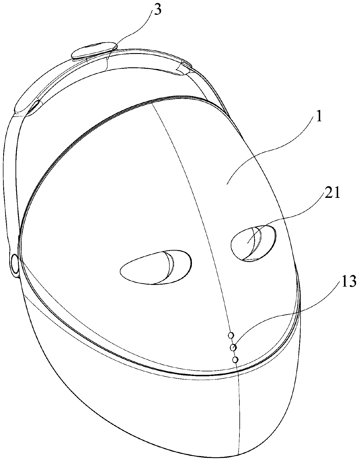
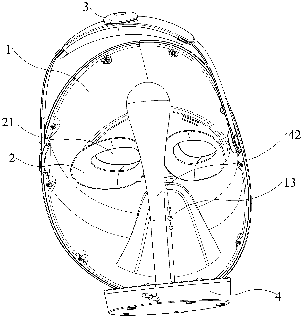
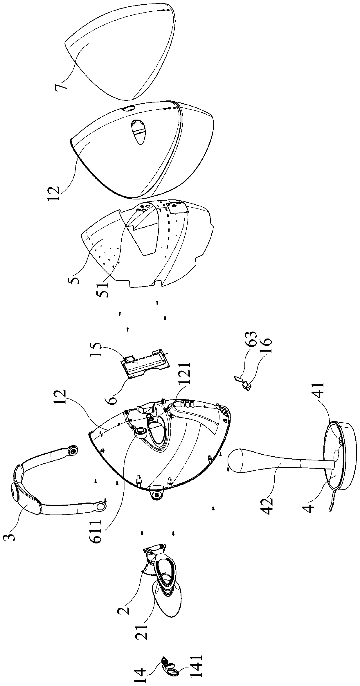
[0050] Such as Figure 1 to Figure 15 As shown, the present invention discloses a beauty mask structure, which includes a mask body 1 and a light shielding eye mask 2 .

[0051] Cooperate Figure 1 to Figure 4 as well as Figure 7 and Figure 8As shown, the mask body 1 includes a light-shielding front cover 11 and a light-transmitting back cover 12, the front cover 11 can be made of light-shielding material, and the back cover 12 can be made of light-transmitting material. The front cover 11 is installed on the front side of the rear cover 12 by clamping, screw locking or welding, and an accommodating cavity 10 is formed between the front cover 11 and the rear cover 12, and the accommodating cavity 10 is installed There are a plurality of LED lamps 51 and a control circuit board 6. The light emitted by each...


PUM


Abstract

The invention discloses a beauty mask structure which comprises a mask body and a light isolation eyeshade; the mask body comprises a light-shading front cover and a light-transmitting rear cover; thefront cover is installed on the front side of the rear cover, and a accommodating cavity is formed between the front cover and the rear cover; a plurality of LED lamps and a control circuit board aremounted in the accommodating cavity; the light isolation eyeshade is mounted on the mask body and penetrates through the front side and the rear side of the mask body; two observation holes which arethrough in the front-back direction are formed in the positions, corresponding to the two eyes of the human body, of the light isolation eyeshade respectively, and the light isolation eyeshade can prevent light emitted by the LED lamps from entering the observation holes. By adoption of the light isolation eyeshade, human eyes can be effectively protected, and it can be guaranteed that a user hasa good visual field in the using process.

Description

technical field [0001] The invention relates to the field of beauty equipment, in particular to a structure of a beauty mask. Background technique [0002] Using light to treat human diseases is a very ancient method. As a new type of light source, LED has a variety of wavelengths. As the biological effects of light sources with different wavelengths are gradually recognized by people, they are gradually being used in medicine and playing an active role. Scientific discoveries and clinical trials have proved that blue light has the effects of treating skin acne, anti-inflammatory acne, shrinking pores, balancing oil secretion, and reducing acne scars; red light can stimulate collagen and elastin, increase skin moisture retention and elasticity, Restore skin vitality, skin tightening and other effects; infrared light has the effects of promoting wound healing, pain relief, deep repair, cell regeneration, anti-inflammatory and anti-allergy. However, when the light of light s...

Claims


Application Information

Patent Timeline
Patent Type & Authority Applications(China)
IPC IPC(8): A61N5/06A61F9/04H05B45/00H02J7/00
CPCA61N5/0616A61F9/045H02J7/0044A61N2005/0647A61N2005/0651A61N2005/0654A61N2005/0626Y02B20/30
Inventor 李文慧卢俊棋陈文强陈名澍
Owner XIAMEN JOYA TECH
Learn More