Structure for dredging concrete mortar in construction steel pipes

A technology for concrete mortar and steel pipes, which is applied to cleaning methods and utensils, cleaning hollow objects, chemical instruments and methods, etc., and can solve the problems of easy deviation from the actual position and large swing of the drill bit.

Active Publication Date: 2020-04-17
ZHEJIANG ZHONGRONG CONSTR CO LTD
View PDF5 Cites 3 Cited by
  • Summary
  • Abstract
  • Description
  • Claims
  • Application Information

AI Technical Summary

Problems solved by technology

[0004] Authorized announcement number CN 207547194 U discloses a concrete mortar dredging structure inside a building steel pipe, which relates to the field of building construction, including a steel pipe poured in concrete, a concrete mortar block blocked in the steel pipe, and a concrete mortar block for removing the concrete. A blockage removal tool for mortar blockage, the blockage removal tool includes an electric drill arranged outside the steel pipe, a flexible shaft connected to the electric dri

Method used


Image

  • Structure for dredging concrete mortar in construction steel pipes
  • Structure for dredging concrete mortar in construction steel pipes
  • Structure for dredging concrete mortar in construction steel pipes

Examples


Embodiment 1

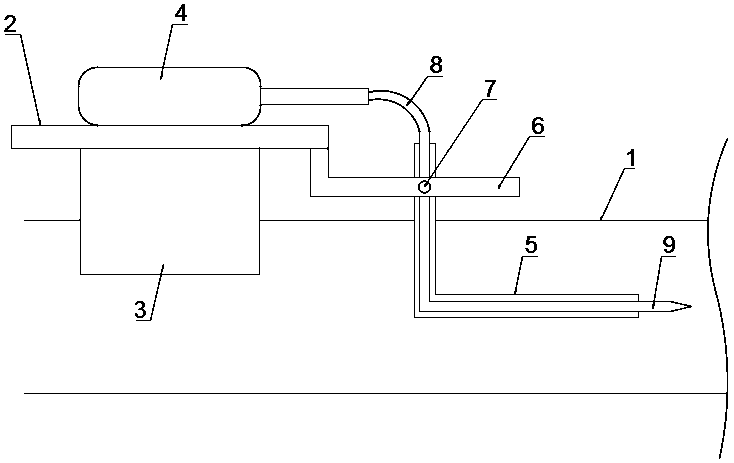
[0022] refer to figure 1 , Figure 4 , a concrete mortar dredging structure inside a building steel pipe, including a mounting plate 2 arranged on the upper side of the steel pipe 1, the lower side of the mounting plate 2 is provided with a fixing mechanism connected to the steel pipe 1, and the fixing mechanism includes two lower side walls connected to the mounting plate 2 Rotate the connected arc plate 3, the upper side wall of the mounting plate 2 is fixed with a telescopic rod 11, the driving end of the telescopic rod 11 is vertically fixed with a U-shaped plate 10, and the two ends of the U-shaped plate 10 extend through the mounting plate 2 to The lower side of the mounting plate 2 is in contact with the outer wall of the arc-shaped plate 3. After the mounting plate 2 is placed on the steel pipe 1, the driving end of the telescopic rod 11 is retracted, driving the U-shaped plate 10 to move downwards, passing through the U-shaped plate 10 two The contact between the end...

Embodiment 2

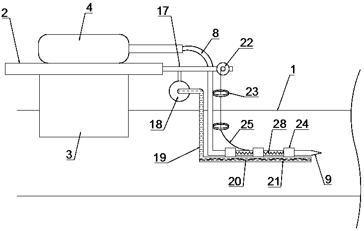
[0026] refer to figure 2 , Figure 4 , a concrete mortar dredging structure inside a building steel pipe, including a mounting plate 2 arranged on the upper side of the steel pipe 1, the lower side of the mounting plate 2 is provided with a fixing mechanism connected to the steel pipe 1, and the fixing mechanism includes two lower side walls connected to the mounting plate 2 Rotate the connected arc plate 3, the upper side wall of the mounting plate 2 is fixed with a telescopic rod 11, the driving end of the telescopic rod 11 is vertically fixed with a U-shaped plate 10, and the two ends of the U-shaped plate 10 extend through the mounting plate 2 to The lower side of the mounting plate 2 is in contact with the outer wall of the arc-shaped plate 3. After the mounting plate 2 is placed on the steel pipe 1, the driving end of the telescopic rod 11 is retracted, driving the U-shaped plate 10 to move downwards, passing through the U-shaped plate 10 two The contact between the en...

Embodiment 3

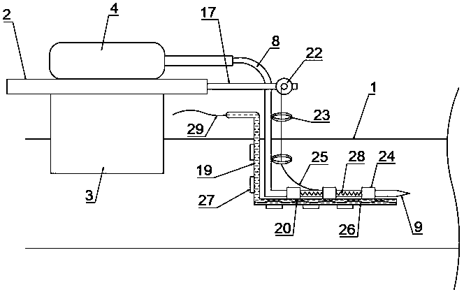
[0030] refer to image 3 , Figure 4 , a concrete mortar dredging structure inside a building steel pipe, including a mounting plate 2 arranged on the upper side of the steel pipe 1, the lower side of the mounting plate 2 is provided with a fixing mechanism connected to the steel pipe 1, and the fixing mechanism includes two lower side walls connected to the mounting plate 2 Rotate the connected arc plate 3, the upper side wall of the mounting plate 2 is fixed with a telescopic rod 11, the driving end of the telescopic rod 11 is vertically fixed with a U-shaped plate 10, and the two ends of the U-shaped plate 10 extend through the mounting plate 2 to The lower side of the mounting plate 2 is in contact with the outer wall of the arc-shaped plate 3. After the mounting plate 2 is placed on the steel pipe 1, the driving end of the telescopic rod 11 is retracted, driving the U-shaped plate 10 to move downwards, passing through the U-shaped plate 10 two The contact between the end...


PUM


Abstract

The invention discloses a structure for dredging concrete mortar in construction steel pipes. The structure comprises a mounting plate which is arranged on the upper side of a steel pipe; a fixing structure which is connected with the steel pipe is arranged on the lower side of the mounting plate; the fixing structure comprises two arc-shaped plates which are rotatably connected with the lower side wall of the mounting plate; an expansion link is fixed on the upper side wall of the mounting plate; the driving end of the expansion link is vertically and upwardly fixed with a U-shaped plate; twoends of the U-shaped plate penetrate through the mounting plate so as to extend to the lower side of the mounting plate and make contact with the outer walls of the arc-shaped plates; a motor I is fixed on the upper side wall of the mounting plate; a soft shaft is fixed at the driving end of the motor I; and the lower end of the soft shaft extends into the steel pipe and is fixed with a drill bit. Through pumping hydraulic oil into an L-shaped pipe or a hose to harden the hose, or electrifying to generate magnetic fields to convert magnetorheological fluids to solid state, the support for thesoft shaft is realized, the soft shaft is ensured to rotate stably, and the drill bit is prevented from deviating from the practical position as the amplitude of swing is too large.

Description

technical field [0001] The invention relates to the technical field of construction, in particular to a concrete mortar dredging structure inside a construction steel pipe. Background technique [0002] Steel pipes for construction can be divided into seamless steel pipes and seamed steel pipes according to the seamlessness of seams. Seamed steel pipes are divided into spiral steel pipes and straight seam steel pipes according to the different welds. The two are widely used in construction piling, structure, steel structure, load-bearing, drainage and other aspects. The main materials are carbon steel, stainless steel, alloy steel. Among them, carbon steel is the most commonly used material, and the main production base is Cangzhou, Hebei. According to the customer's requirements, the length of the steel pipe can be fixed or loose. The price of the fixed length is 500-600 yuan more expensive per ton than the loose length. According to the production method, construction s...

Claims


Application Information

Patent Timeline
IPC IPC(8): B08B9/051B08B13/00
CPCB08B9/051B08B13/00
Inventor 张素勉
Owner ZHEJIANG ZHONGRONG CONSTR CO LTD
Why Eureka
Try Eureka