
Copper bar production process

A production process and technology for copper rods, applied in metal rolling and other directions, can solve the problems of unutilized heat and heat waste, and achieve the effects of improving utilization, improving combustion efficiency, and high combustion heat.

Active Publication Date: 2020-04-17
HANGZHOU FUTONG ELECTRIC WIRE & CABLE
View PDF10 Cites 2 Cited by
  • Summary
  • Abstract
  • Description
  • Claims
  • Application Information

AI Technical Summary

Problems solved by technology

[0003] In view of the above problems, the present invention proposes a copper rod production process, which solves the problem that the tail gas produced by the combustion of combustible gas in the existing copper rod production process carries a large amount of heat. The heat is not utilized but is directly discharged to the outside, causing heat wasteful defect

Method used


Image

  • Copper bar production process
  • Copper bar production process
  • Copper bar production process

Examples


Embodiment 1

[0030] The invention discloses a copper rod production process, comprising the following steps:

[0031] 1) Copper melting process: use the copper plate preheating furnace to melt the copper plate 100 into molten copper, during which the high-temperature exhaust gas after combustion is returned to the nozzle, preheating the gas in the outer air guide pipe and the inner air guide pipe, and increasing the outer air guide pipe And the air pressure in the inner air guide pipe, the gas flowing out of the nozzle enters the preheating chamber of the combustion chamber of the copper plate preheating furnace to preheat the copper plate to be melted;

[0032] 2) Rod casting process: casting the molten copper on the surface of the core rod to generate a cast rod;

[0033] 3) Hot-rolling process: hot-rolling the cooled cast rod to generate a copper rod;

[0034] 4) Winding process: wind the above-mentioned copper rod into a circle.

Embodiment 2

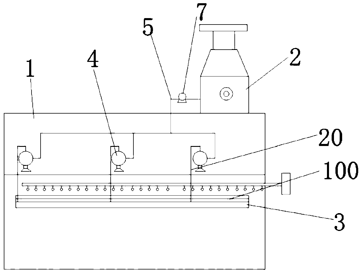
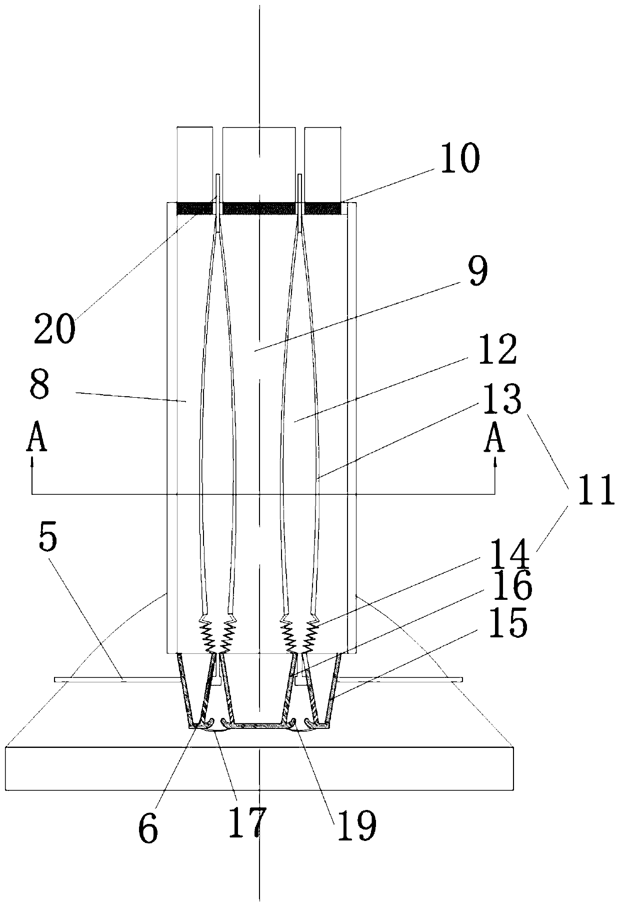
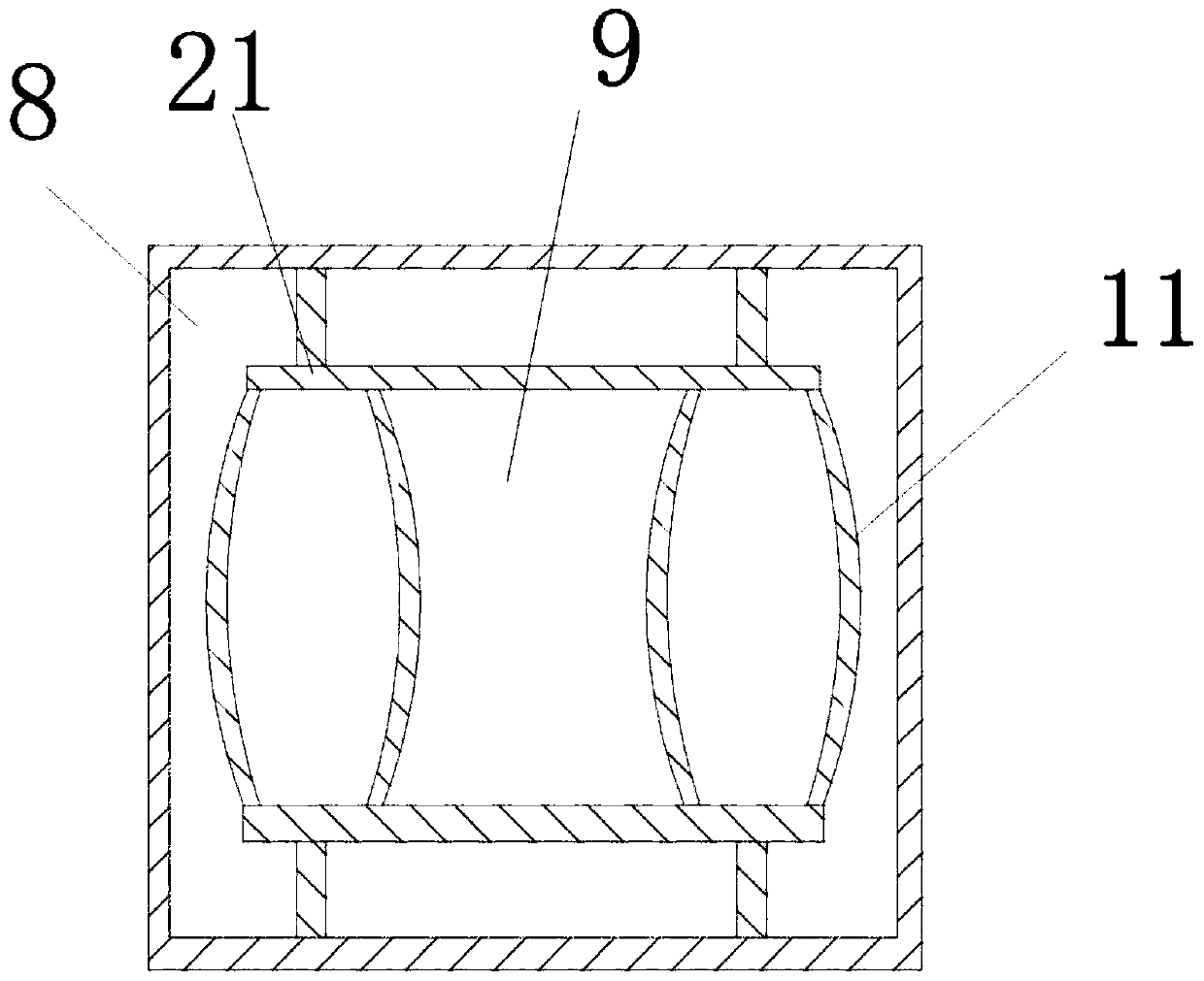
[0036] Such as figure 1 , figure 2 , image 3 and Figure 4 , the present invention also discloses a copper plate preheating furnace, comprising: a combustion chamber 1 and a smoke exhaust device 2 installed on the top of the combustion chamber; the bottom of the combustion chamber is equipped with a preheating chamber 3, the upper part of the preheating chamber A copper plate 100 is installed; a nozzle 4 is installed on the upper part of the combustion chamber, and the smoke exhaust device is connected to the nozzle through the return pipeline 5, and the nozzle is connected to the preheating chamber 6 through the intake pipeline 20, and the return pipeline is equipped with a pressurized pump 7;

[0037] The nozzle includes an outer air guide pipe 8 with a combustible gas and an inner air guide pipe 9 with a combustion-supporting gas. The end of the outer air guide pipe and the inner air guide pipe near the intake side is equipped with a one-way valve 10. The one-way valv...


PUM


Abstract

The invention relates to a copper bar production process which comprises the following steps of (1) melting copper: using a copper plate preheating furnace for melting a copper plate into molten copper, reflowing high-temperature waste gas after combustion into a nozzle in the period, preheating gas in an outer gas guiding pipe and an inner gas guiding pipe, increasing gas pressure in the outer gas guiding pipe and the inner gas guiding pipe, feeding the gas flowing out through the nozzle into a preheating chamber of a combustion chamber of the preheating furnace, and preheating a copper plateto be melted; (2) casting a rod: casting the molten copper to the surface of a core rod, and generating the casting rod; (3) hot-rolling: carrying out hot-rolling treatment on the cooled casting rod,and generating a copper rod; and (4) winding: winding the copper rod into a coil. According to the copper bar production process provided by the invention, the high-temperature waste gas reflows intothe nozzle and flows out through the nozzle to enter the preheating chamber so as to preheat the copper plate, so that the heat is recycled, and the utilization ratio of the heat is improved.

Description

technical field [0001] The invention relates to the field of copper rod production, in particular to a copper rod production process. Background technique [0002] In the existing copper rod preparation process, the copper plate is heated through the copper plate preheating furnace; during this period, the exhaust gas generated by the combustion of combustible gas in the combustion chamber carries a large amount of heat, and the heat is not used but directly discharged to the outside, which is resulting in a waste of heat. Contents of the invention [0003] In view of the above problems, the present invention proposes a copper rod production process, which solves the problem that the tail gas produced by the combustion of combustible gas in the existing copper rod production process carries a large amount of heat. The heat is not utilized but is directly discharged to the outside, causing heat wasteful flaws. [0004] The technical scheme that the present invention takes...

Claims


Application Information

Patent Timeline
Patent Type & Authority Applications(China)
IPC IPC(8): B21B1/46B21B1/16B21C37/04B22D19/08
CPCB21B1/16B21B1/463B21C37/04B22D19/08
Inventor 王醒东郝小龙华瑶
Owner HANGZHOU FUTONG ELECTRIC WIRE & CABLE
Learn More