Production system of hoisting anchor rod and process thereof

A production system and technology for hanging bolts, which are applied in other manufacturing equipment/tools, manufacturing tools, metal processing equipment, etc., can solve the problems of low processing efficiency, complicated operation, and cumbersome process, and achieve the effect of improving work efficiency.

Active Publication Date: 2020-04-17
青岛建邦士金属制品有限公司
View PDF6 Cites 0 Cited by
  • Summary
  • Abstract
  • Description
  • Claims
  • Application Information

AI Technical Summary

Problems solved by technology

[0004] The fixing bolt disclosed in the above-mentioned prior art is a kind of lifting anchor. This type of lifting anchor generally adopts long steel bars during production, cuts them into equidistant steel columns, and heats one end of the steel bars. After heating one end of the steel bar, forge the heated end of the steel bar, and then wait for cooling. After forming one end of the steel bar, heat the other end of the steel bar. After the heating is completed, then forge the steel bar The heating end is forged again, which requires multiple people to operate, and the process is cumbersome, the operation is more complicated, and the processing efficiency is low

Method used


Image

  • Production system of hoisting anchor rod and process thereof
  • Production system of hoisting anchor rod and process thereof
  • Production system of hoisting anchor rod and process thereof

Examples


Embodiment 1

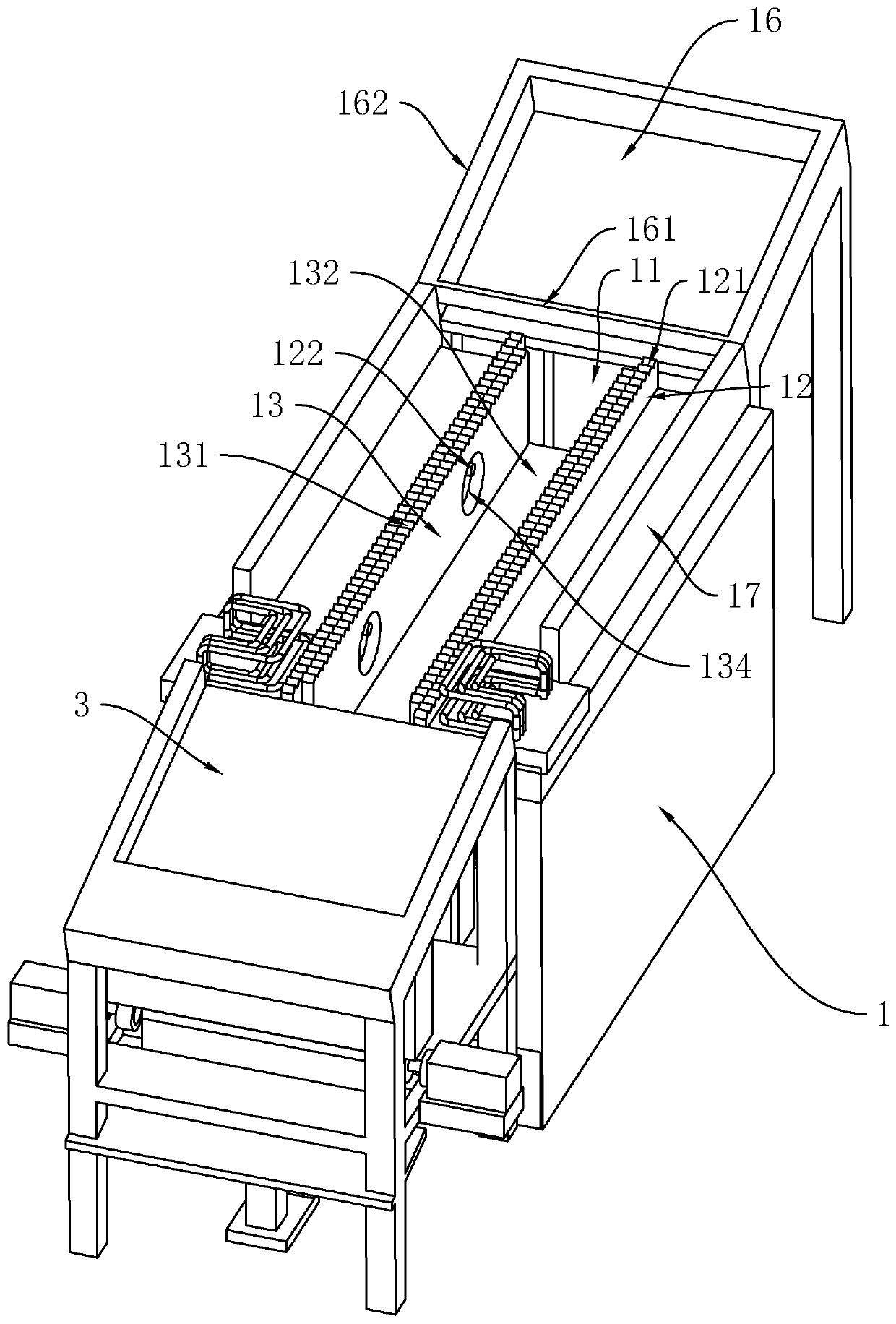
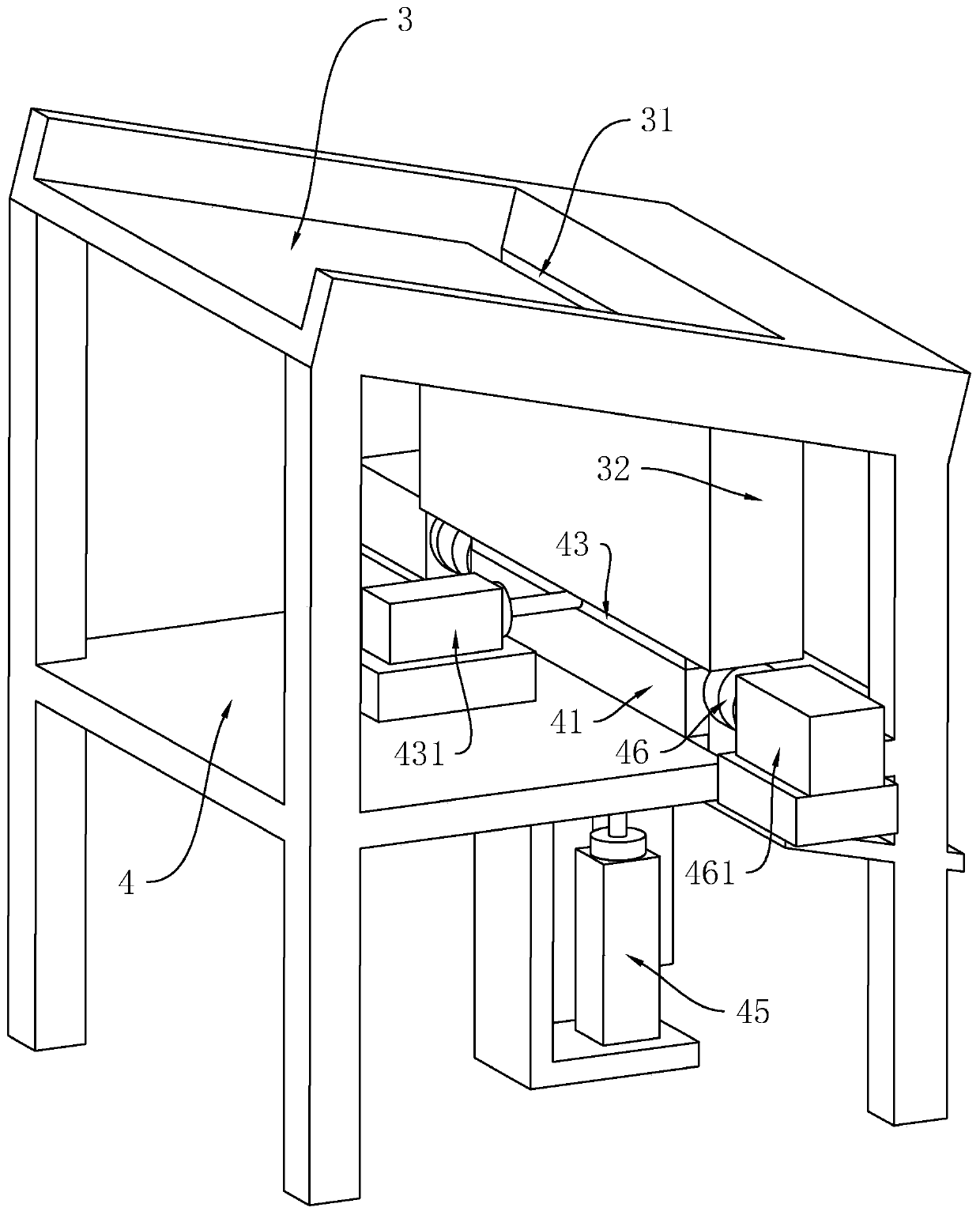
[0043] Embodiment one: refer to figure 1 , a production system for lifting anchor rods, including automatic feeding heating equipment and molding equipment.

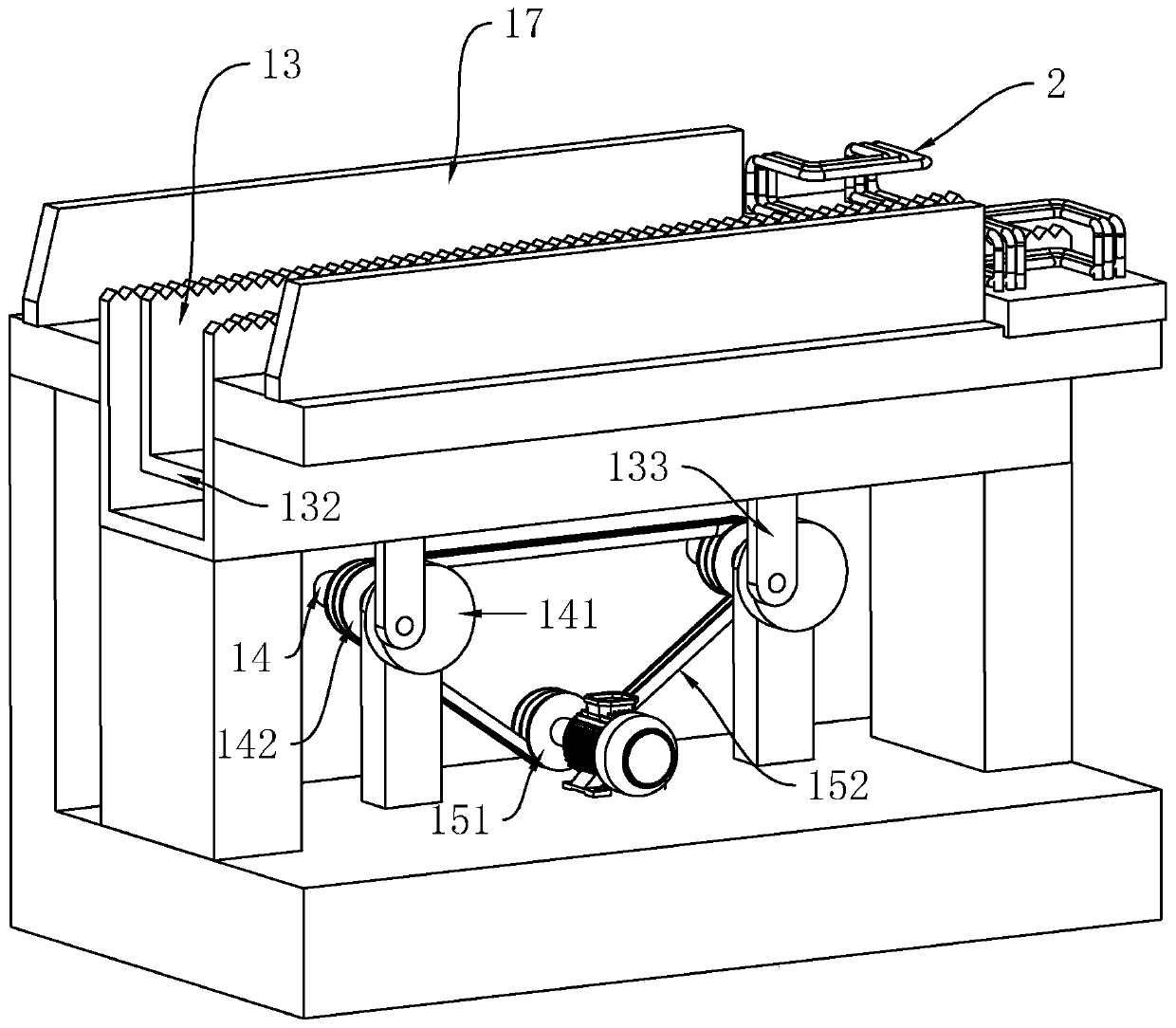
[0044] refer to figure 1 and figure 2 , the automatic heating device comprises a rectangular bottom frame 1, the middle part of the bottom frame 1 is provided with a long groove 11, the length direction of the long groove 11 is the same as that of the bottom frame 1, and the two sides of the bottom frame 1 corresponding to the long groove 11 are all vertical The support plate 12 is fixedly connected, and the length direction of the support plate 12 is the same as the length direction of the long groove 11. The upper sides of the two support plates 12 are evenly provided with corresponding tooth grooves 121 along the length direction of the support plate 12, and the long groove 11 Both sides of the feed plate 13 are vertically provided with the feed plate 13 whose length direction is the same as the length direction of...

Embodiment 2

[0053] Embodiment 2: a production process for a lifting anchor disclosed by the present invention, comprising the following steps:

[0054] Step 1, cut into sections, cut the long steel bar into several steel columns according to the same length;

[0055] Step 2, heating, transfer the steel column in sequence and heat the two ends of the steel column respectively;

[0056] Step 3, forming, fixing the middle part of the steel column, and making the two ends of the steel column respectively have the length of the heating section, and then simultaneously pressing the two ends of the steel column inward to form a disc-shaped end;

[0057] Step 4. Cooling. Take out the formed steel columns at both ends and cool them down.

[0058] The implementation principle of this embodiment is: when processing the anchor rod, both ends of the steel column need to be heated, and then extruded at the same time. The operation is simple, and the technical level of the workers is greatly reduced, a...


PUM


Abstract

The invention relates to a production system of a hoisting anchor rod and a process thereof. The system comprises an automatic feeding and heating device capable of heating two ends of a steel columnand a forming device, wherein the forming device comprises a bottom plate and two shaping plates fixedly connected with an upper side of the bottom plate, a shaping groove of which the width is the same as the diameter of the steel column is formed between the two shaping plates, a sealing plate capable of sealing an upper side of the shaping groove along with sliding is arranged on an upper sideof the shaping groove, a through groove is formed in a position, corresponding to the shaping groove, of the bottom plate, an inserting block which moves upwards, can penetrate through the through groove and is inserted into the shaping groove is further arranged on a lower side of the bottom plate, one side of an upper surface of the inserting block is obliquely arranged downwards, two ends, corresponding to the shaping groove, of the bottom plate are further provided with ejector blocks capable of moving in the approaching direction, and the sides, close to each other, of the ejector blocksare further provided with circular shaping grooves. The system is advantaged in that heating, placing and forging of two ends of an anchor rod can be achieved at the same time, and unmanned operationis achieved under automatic operation of a manipulator.

Description

technical field [0001] The invention relates to the technical field of production of lifting anchors, in particular to a production system of lifting anchors and a process thereof. Background technique [0002] The lifting anchor is part of the lifting and anchoring system, which is mainly used for the lifting of concrete parts. When the concrete member is forming, one end of the anchor rod of the anchoring and lifting system is pre-embedded inside the member. After the concrete is formed to reach the design strength, that is It can be hoisted by anchor rod. [0003] The existing authorization announcement number that can be referred to is: Chinese utility model patent CN203998588U, which discloses a prefabricated concrete wall panel hoisting part, which is composed of a fixing bolt, an auxiliary fixing part, and a pull ring. The head stud shape is an integral structure composed of upper, middle and lower parts; the auxiliary fixing part is a hemispherical part composed of ...

Claims


Application Information

Patent Timeline
Patent Type & Authority Applications(China)
IPC IPC(8): B21J1/06B21J13/08B21J13/00B21J5/06B23P23/04
CPCB21J1/06B21J5/06B21J13/00B21J13/08B23P23/04
Inventor 于永杰刘治国
Owner 青岛建邦士金属制品有限公司
Why Eureka
Try Eureka