A self-feeding, multi-function, spring-up gear ring friction plate attachment mechanism

An automatic feeding and multi-functional technology, which is applied in the field of auto parts manufacturing, can solve problems affecting product quality and prone to cracking, and achieve the effects of beautifying equipment, ensuring product quality, and low equipment cost

Active Publication Date: 2020-11-20
NORTHWESTERN POLYTECHNICAL UNIV
View PDF10 Cites 0 Cited by
  • Summary
  • Abstract
  • Description
  • Claims
  • Application Information

AI Technical Summary

Problems solved by technology

[0006] In order to avoid the deficiencies of the prior art, the present invention proposes an automatic feeding multi-functional elastic gear ring friction plate attachment mechanism, which overcomes the shortcomings of the existing hand-attached paper-based friction material for the synchronizer gear ring and solves its problems. In the process of attaching, it is easy to break and affect the quality of the product. A self-feeding, multi-function, elastic-raised gear ring friction plate attachment mechanism is proposed; the invention mainly uses the gear transmission system combined with the plane thread to realize the attachment of the slider. The movement, so as to use the attachment slider to complete the attachment action

Method used


Image

  • A self-feeding, multi-function, spring-up gear ring friction plate attachment mechanism
  • A self-feeding, multi-function, spring-up gear ring friction plate attachment mechanism
  • A self-feeding, multi-function, spring-up gear ring friction plate attachment mechanism

Examples


Embodiment Construction

[0044] The embodiments described below by referring to the figures are exemplary and are intended to explain the present invention and should not be construed as limiting the present invention.

[0045] In describing the present invention, it should be understood that the terms "center", "longitudinal", "transverse", "length", "width", "thickness", "upper", "lower", "front", " Orientation indicated by rear, left, right, vertical, horizontal, top, bottom, inside, outside, clockwise, counterclockwise, etc. The positional relationship is based on the orientation or positional relationship shown in the drawings, which is only for the convenience of describing the present invention and simplifying the description, rather than indicating or implying that the referred device or element must have a specific orientation, be constructed and operated in a specific orientation, Therefore, it should not be construed as limiting the invention.

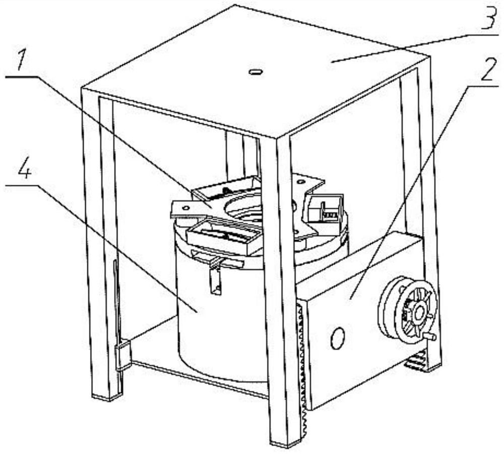
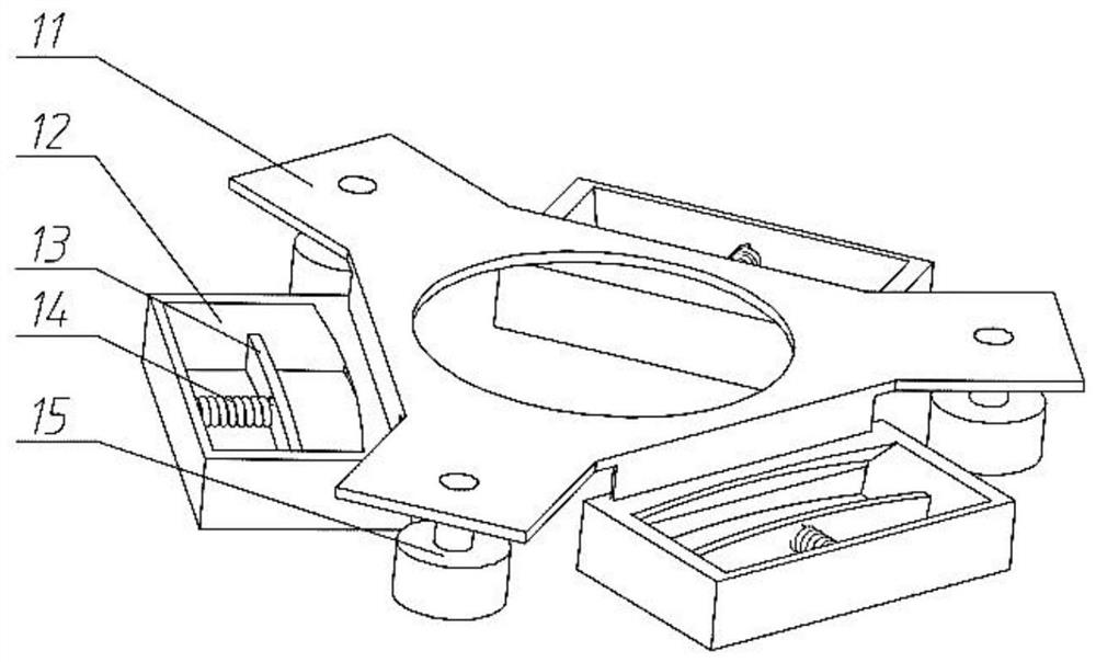
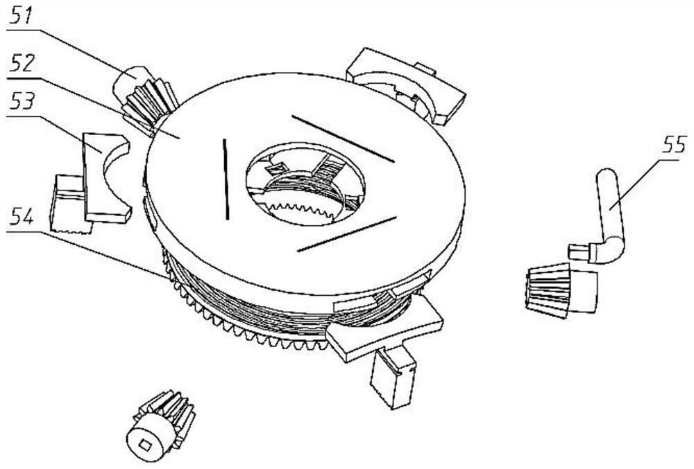
[0046] refer to Figure 1-Figure 8 , a self...


PUM


Abstract

The invention discloses a multifunctional gear ring friction plate attaching mechanism capable of realizing automatic feeding and bouncing, and belongs to the field of automobile part manufacturing. The gear ring friction plate attaching mechanism comprises an external material feeding mechanism, an external material attaching mechanism, an internal material attaching mechanism, a positioning andbouncing mechanism, a lifting mechanism and the like; an external material feeding inserting plate of the external material feeding mechanism inserts a friction material into a material bending attaching groove, and a material pushing plate carries out feeding; the external material attaching mechanism is composed of a material bending disc, an external material bending attaching sliding block, abevel gear disc, a small bevel gear and the like, wherein the small bevel gear is rotated to drive the sliding block to move so as to press the material in the material bending attaching groove to a gear ring, so that attachment is achieved; the internal material attaching mechanism is similar to the external material attaching mechanism; the positioning and bouncing mechanism is composed of springs and positioning blocks; and the lifting mechanism adopts gear and rack transmission so as to be matched with the use of an internal material forming mechanism. According to the mechanism, the mechanical structure is used for achieving the attachment of the gear ring paper-based friction material, the defect that the material is prone to be cracked in the manual bending process is overcome, andthe productivity is greatly improved.

Description

technical field [0001] The invention belongs to the field of automobile parts manufacturing, and in particular relates to an automatic feeding multifunctional and elastically lifting gear ring friction plate attachment mechanism. Background technique [0002] The synchronizer is a very important part in the automobile transmission. Its function is to make the gears to be meshed reach a consistent speed and then mesh smoothly. The synchronizer is divided into normal pressure type, inertia type and self-energizing type. At present, friction inertia synchronizer is widely used , The inertial synchronizer is synchronized by friction, and the ring gear is the core component of the synchronizer to achieve friction. [0003] At present, the most commonly used gear ring is the attached gear ring, that is, a layer of friction material is attached to the friction surface. The common friction material is carbon fiber cloth. Although it has many excellent properties, the cost of carbon ...

Claims


Application Information

Patent Timeline
Patent Type & Authority Patents(China)
IPC IPC(8): F16B11/00F16D69/04
CPCF16B11/006F16D69/04F16D2069/045
Inventor 齐乐华郑利强张晓博傅业伟李贺军付前刚张磊磊
Owner NORTHWESTERN POLYTECHNICAL UNIV
Why Eureka
Try Eureka