Upper and lower disc spherical surface polishing mechanism for 3D optical element polishing machine

A technology of optical components and polishing mechanism, which is applied in the direction of optical components, surface polishing machine tools, optical surface grinders, etc., can solve the problems of low production efficiency, high cost, and inability to meet the mass production of multiple varieties of 3D components, and achieve production efficiency High, improve production efficiency, overcome the effect of unqualified polishing

Pending Publication Date: 2020-04-17
王丁
View PDF0 Cites 0 Cited by
  • Summary
  • Abstract
  • Description
  • Claims
  • Application Information

AI Technical Summary

Problems solved by technology

[0004] According to reports, a polishing machine newly developed in South Korea can only polish qualified two-fold mobile phone cover plates, and the polishing of multi-fold 3D components will not work. The disadvantages are low production efficiency and high cost. , far from being able to meet the domestic and foreign demands for mass production of multiple varieties of 3D components, in view of the status quo of polishing 3D components at home and abroad, it is imperative to solve this technical problem

Method used


Image

  • Upper and lower disc spherical surface polishing mechanism for 3D optical element polishing machine
  • Upper and lower disc spherical surface polishing mechanism for 3D optical element polishing machine
  • Upper and lower disc spherical surface polishing mechanism for 3D optical element polishing machine

Examples


Embodiment Construction

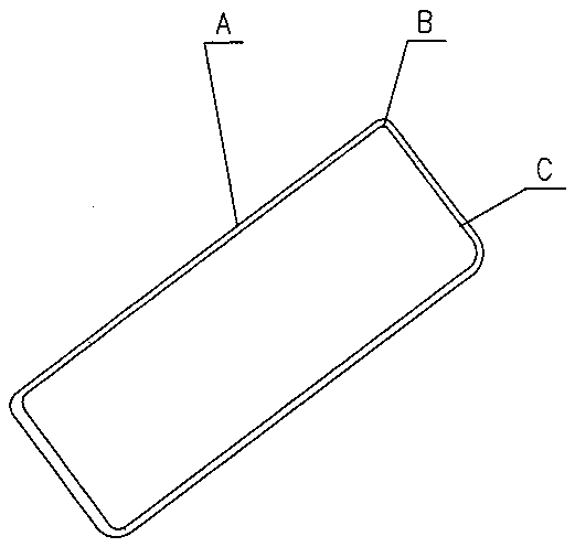
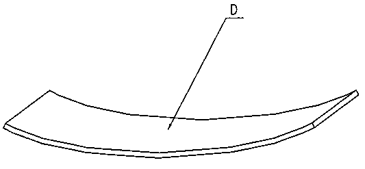
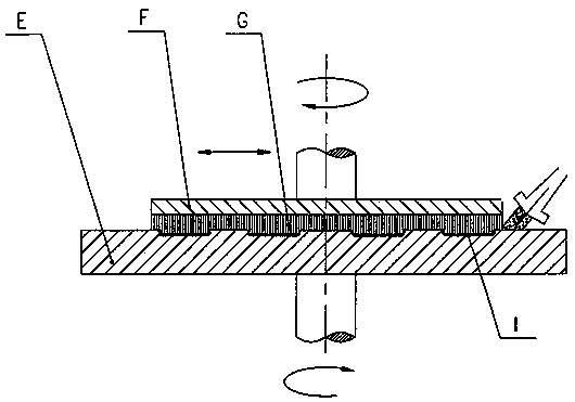
[0021] refer to Figure 4 , 1 , the main technical solution of the present invention is described: the present invention makes the workpiece lower plate 3 cooperate with the spherical brush 18 of the same curvature radius, and the folded surface A of the 3D element, the rounded part B between the folded surfaces and the The rounded portion C between the folding surface and the bottom surface is always subjected to the force of the brush, and is directly and effectively polished by the brush. The polishing mechanism of the present invention includes a first waterproof cover 1, a lower plate base 2, a workpiece lower plate 3, a brush plate base 4, a cover plate 5, a connecting bar 6, a ball valve 7, a second self-aligning bearing 8, a joint 9, a bearing pressure Cover 10, hexagonal nut 11, upper plate short shaft 12, screw 13, upper swing arm 14, second waterproof cover 15, water diversion ring 16, sealing ring 17, spherical brush 18, vacuum suction pipe 19, rotating main shaft...


PUM


Abstract

The invention discloses an upper and lower disc spherical surface polishing mechanism for a 3D optical element polishing machine. The upper and lower disc spherical surface polishing mechanism is mainly used for the 3D special-shaped optical element polishing machine. According to the main technical scheme, in a short shaft, an upper swing arm is connected, a second aligning bearing is arranged between a cover plate and the short shaft, the cover plate is connected with a brush disc base, a spherical brush matched with the spherical brush disc base is adhered to the spherical surface of the brush disc base, a workpiece lower disc matched with the spherical brush is coaxially arranged with the spherical brush, the workpiece lower disc is connected with the lower disc base, the lower disc base is connected with a rotating main shaft, a vacuum suction pipe is arranged in a hole of the rotating main shaft, and a ball valve is connected to a second waterproof cover. The upper and lower discspherical surface polishing mechanism proves by trial that the phenomenon that the polishing of the 3D element is not qualified is fundamentally overcome, the technical quality of the polishing of the 3D element is effectively improved, the production efficiency is improved, the cost is reduced, and the requirement of mass production of multiple varieties of the 3D element is met.

Description

technical field [0001] The invention relates to a polishing mechanism of an optical element polishing machine, which is mainly used for the upper and lower spherical surface polishing mechanisms of a 3D special-shaped optical element polishing machine, and can also be used for a polishing mechanism similar to a polishing machine. Background technique [0002] Shaped optical components mainly refer to optical components with three-dimensional shapes, such as figure 1 The four-sided folded front and rear covers of the mobile phone, such as figure 2 For the curved bracelet shown, the included angle of the four sides can be 90° o , can also be greater than 90 o , There are also watch covers with folded surfaces on the circumference, display window covers, etc. [0003] Special-shaped optical components (hereinafter referred to as 3D components), which make optical products have a more beautiful appearance and excellent physical properties, such as anti-interference, drop res...

Claims


Application Information

Patent Timeline
Patent Type & Authority Applications(China)
IPC IPC(8): B24B13/005B24B13/01B24B27/00B24B29/00B24B41/06
CPCB24B13/0052B24B13/012B24B27/0076B24B29/005B24B41/06
Inventor 王安全王丁
Owner 王丁
Why Eureka
Try Eureka