Clamping device for straw machining

A technology for clamping devices and straws, which is applied in the direction of workpiece clamping devices and manufacturing tools, and can solve the problem that the clamping device does not have a splicing adjustment and fixing structure, reduces the working efficiency of the clamping device, and cannot clamp the straw according to the required type and other issues to achieve the effect of improving the scope of application

Active Publication Date: 2020-04-17
阜南县顺昌塑业有限公司
View PDF10 Cites 2 Cited by
  • Summary
  • Abstract
  • Description
  • Claims
  • Application Information

AI Technical Summary

Problems solved by technology

[0004] The existing clamping device for straw processing has certain disadvantages during use. The base of the traditional clamping device adopts an integrated fixed structure design, so that the traditional clamping device can only fix the corresponding type of straw, allowing users to The clamping device cannot be telescopically adjusted according to the type of straw to be clamped, which reduces the flexibility of the clamping device in use; secondly, the traditional clamping device does not have a splicing adjustment and fixing structure, which makes it impossible for the user to adjust according to the needs of the user. The position of the forming structure of the clamping device can be adjusted arbitrarily, which reduces the scope of application of the clamping device; at the same time, the traditional clamping device does not have an auxiliary docking structure, so that the traditional clamping device cannot complete the clamping and fixing operation of multiple sets of straws at one time, reducing the The working efficiency of the clamping device brings certain adverse effects to the user

Method used


Image

  • Clamping device for straw machining
  • Clamping device for straw machining
  • Clamping device for straw machining

Examples


Embodiment Construction

[0033] The technical solutions in the embodiments of the present invention will be clearly and completely described below in conjunction with the embodiments of the present invention. Apparently, the described embodiments are only some of the embodiments of the present invention, not all of them. Based on the embodiments of the present invention, all other embodiments obtained by persons of ordinary skill in the art without creative efforts fall within the protection scope of the present invention.

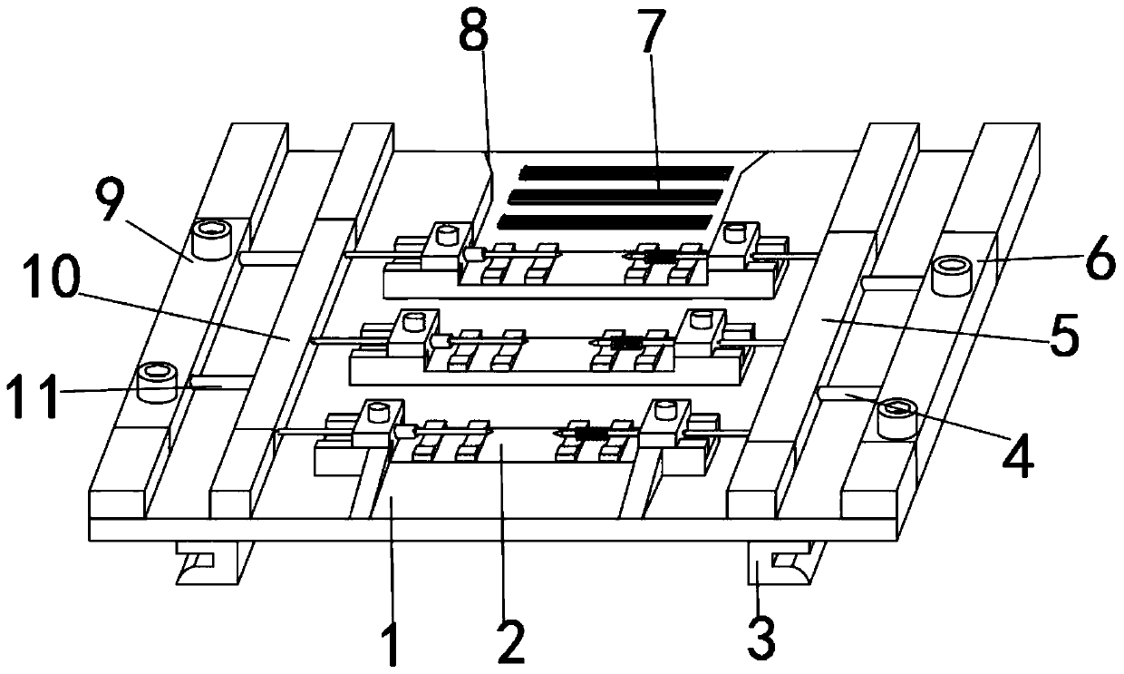
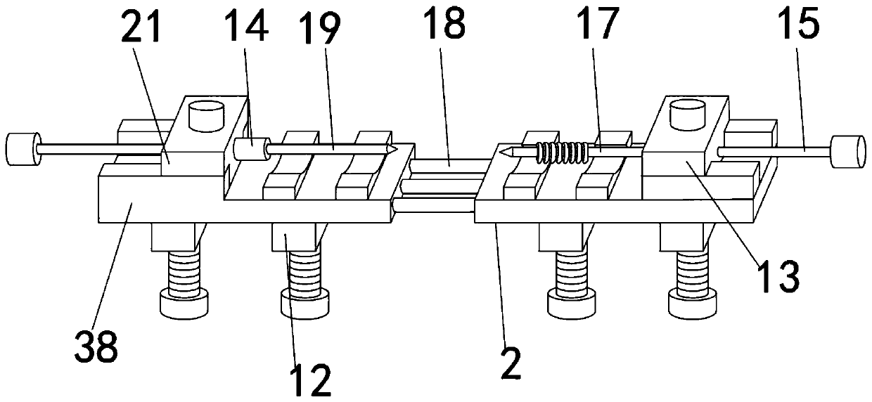
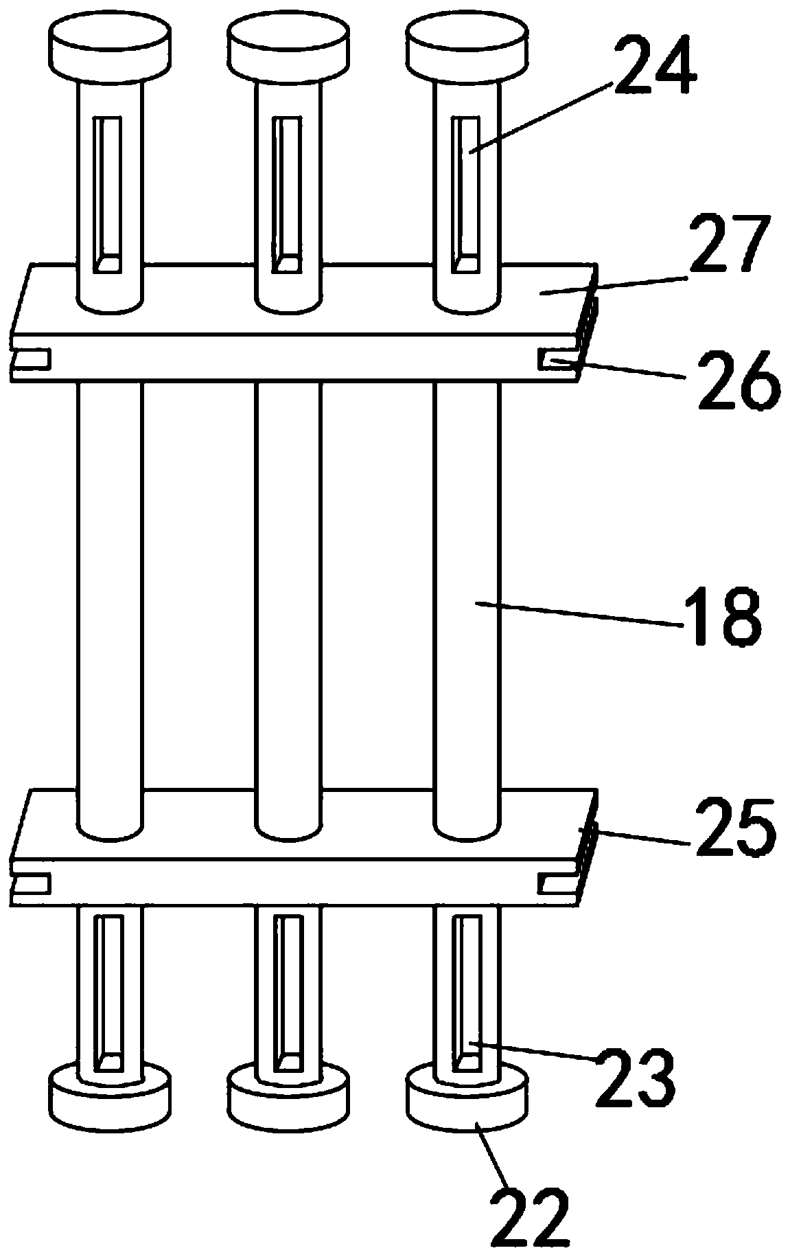
[0034] like Figure 1-6 As shown, a clamping device for straw processing includes a clamping assembly 2, a splicing bottom plate 1 and an inner sleeve rod 18, the clamping assembly 2 is fixedly installed on the upper outer surface of the splicing bottom plate 1, and the clamping assembly 2 is slid by Bottom plate 38, first slide block 13 and second slide block 21 are formed, and first slide block 13 and second slide block 21 are all movably installed on the upper outer surface of ...


PUM


Abstract

The invention discloses a clamping device for straw machining. The device comprises a clamping assembly, a splicing bottom plate and an inner sleeve rod, and the clamping assembly is fixedly installedon the outer surface of the upper end of the splicing bottom plate. The clamping assembly is composed of a sliding bottom plate, a first sliding block and a second sliding block. The first sliding block and the second sliding block are both movably installed on the outer surface of the upper portion of the sliding bottom plate. The first sliding block and the second sliding block are arranged side by side, a forming needle is fixedly installed in the middle of the outer surface of one side of the first sliding block, a conical head is fixedly installed at one end of the forming needle, a shaping pipe is fixedly installed between the forming needle and the conical head, and connecting buckles are fixedly installed on the outer surfaces of the two ends of the shaping pipe. According to theclamping device for straw machining, the clamping device for straw machining is provided with a telescopic adjusting structure, the flexibility of the clamping device during use is improved, meanwhile, the clamping device is provided with a splicing type combined structure, and the application range of the clamping device is widened.

Description

technical field [0001] The invention belongs to the field of clamping devices, in particular to a clamping device for straw processing. Background technique [0002] The clamping device for straw processing is a kind of clamping device that assists in the fixing operation of the straw during the rolling process of the straw, so as to prevent the inclination of the straw during the rolling process. It can be fixed by the two ends of the straw, so that the straw is in a relatively fixed state during the rolling process. [0003] A clamping device disclosed in the comparative document CN104101173B, the clamping device includes a base fixed on the inner wall of the refrigerator, a positioning piece arranged opposite to the base and against the side wall of the drawer, and is arranged between the base and the positioning piece and holds the positioning piece The elastic device is always in contact with the side wall of the drawer. The base includes a base plate fixed on the inne...

Claims


Application Information

Patent Timeline
Patent Type & Authority Applications(China)
IPC IPC(8): B25B11/00B29C37/00
CPCB25B11/00B29C37/00
Inventor 鞠少军
Owner 阜南县顺昌塑业有限公司
Why Eureka
Try Eureka