
Vertical stirring tank for heating and slurrying of sludge

A technology for stirring tanks and sludge, applied in pyrolysis treatment of sludge, mixers with rotating stirring devices, chemical instruments and methods, etc., can solve the problems affecting the stable operation of production, leakage of sludge and odor, sealing packing Leakage and other problems, to achieve the effect of long-term stable operation, small footprint, and good airtight performance

Pending Publication Date: 2020-04-17
HUNAN JUNXIN ENVIRONMENTAL PROTECTION CO LTD
View PDF5 Cites 0 Cited by
  • Summary
  • Abstract
  • Description
  • Claims
  • Application Information

AI Technical Summary

Problems solved by technology

[0004] 1) The sealing packing of the stirring drive shaft of the horizontal pulper is prone to leakage, resulting in the leakage of sludge and odor;
[0005] 2) The transmission shaft is driven by a universal joint in the tank, without lubrication and easy to wear, the main and driven shafts need to be repaired and replaced every six months
It takes 3-7 days for each repair, which affects the stable operation of production

Method used


Image

  • Vertical stirring tank for heating and slurrying of sludge
  • Vertical stirring tank for heating and slurrying of sludge
  • Vertical stirring tank for heating and slurrying of sludge

Examples


Embodiment Construction

[0025] The present invention will be described in further detail below in conjunction with the accompanying drawings and specific embodiments.

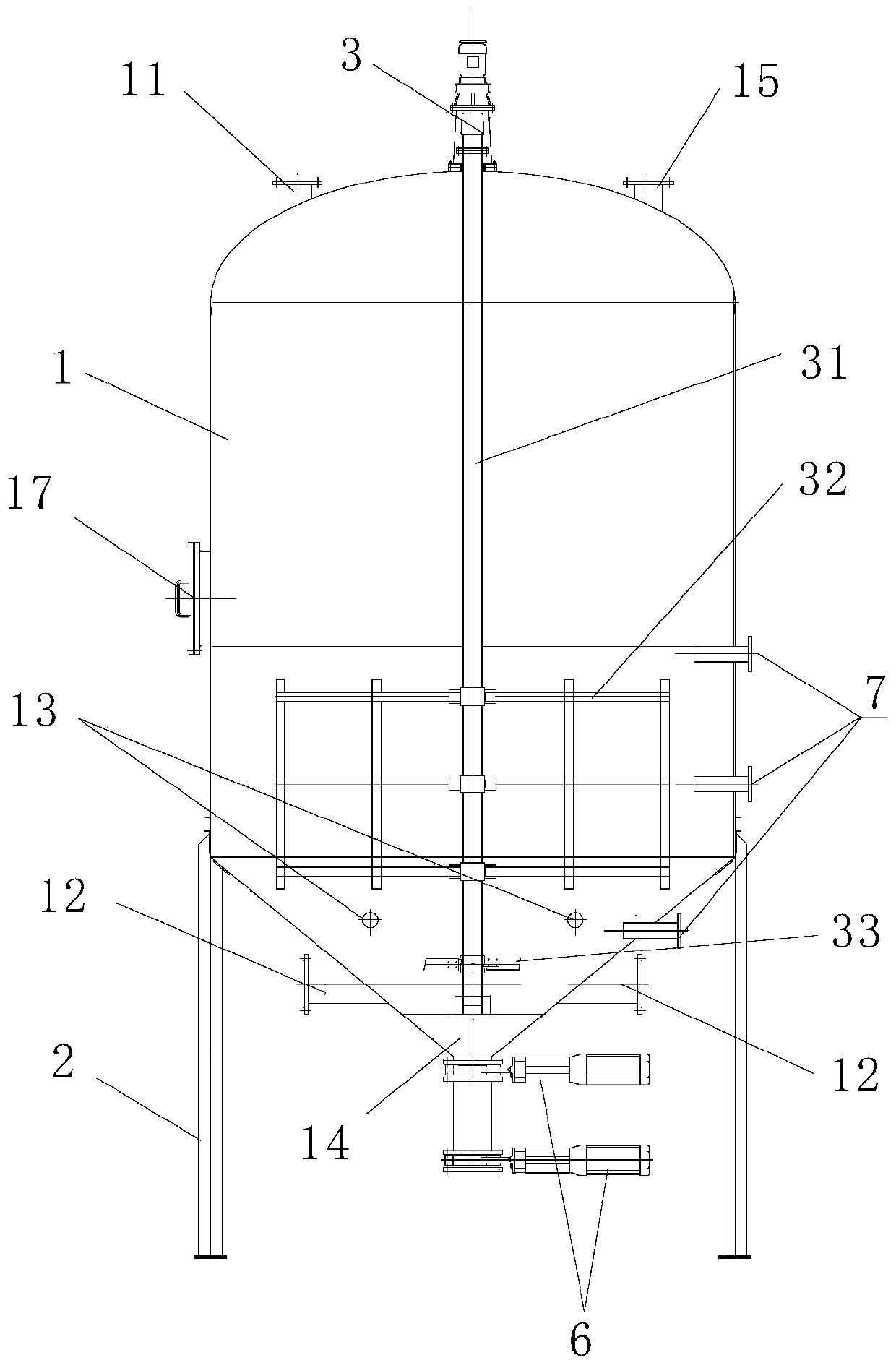
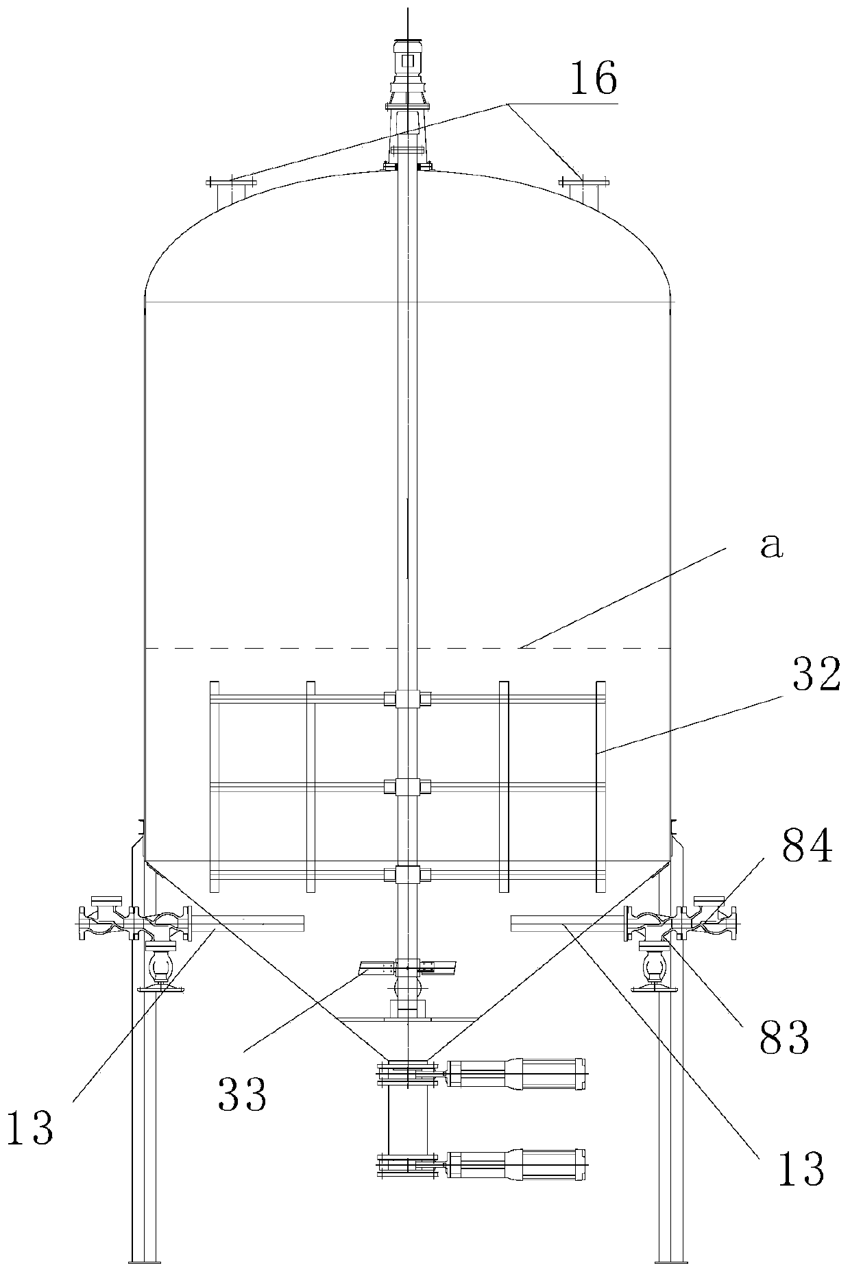
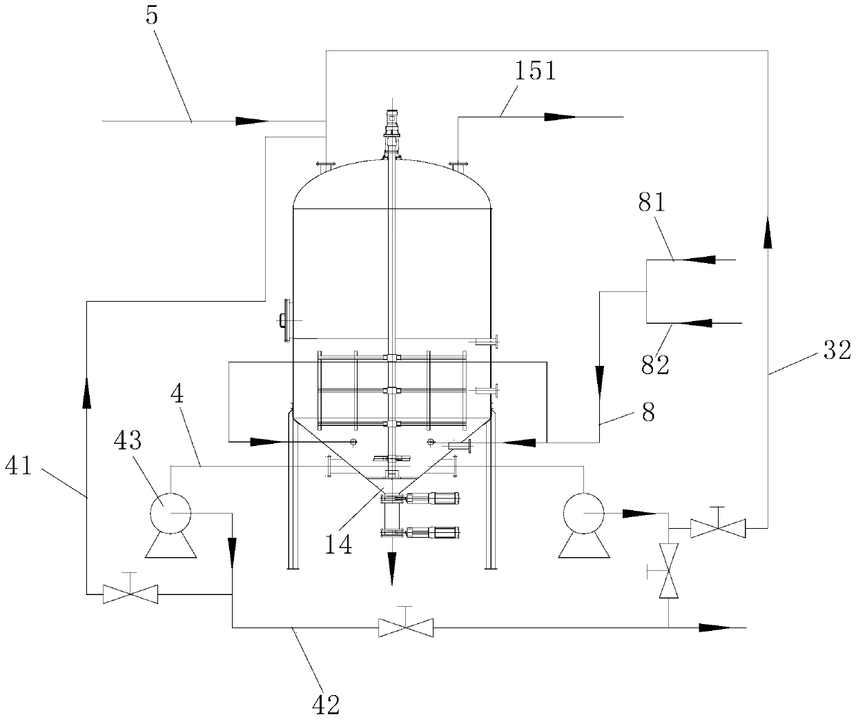
[0026] Such as figure 1 and figure 2 As shown, the vertical stirring tank for sludge heating and slurrying in this embodiment includes a tank body 1, a bracket 2 and a stirring assembly 3. The stirring assembly 3 includes a stirring shaft 31, a stirring frame 32 and paddles 33. The stirring shaft 31 is Vertical, and located in the tank body 1, the stirring frame 32 and the paddle 33 are all arranged on the stirring shaft 31, and the paddle 33 is located at the lower end of the stirring frame 32, the upper part of the tank body 1 is provided with a sludge inlet 11, and the lower part is provided with There are sludge outlet 12, steam inlet 13 and sand outlet 14, and the sand outlet 14 is located below the sludge outlet 12, and the sludge outlet 12 is provided with a sludge outlet 4 and a sludge outlet pump on the sludge outlet 4 43....


PUM


Abstract

The invention discloses a vertical stirring tank for heating and slurrying of sludge. The vertical stirring tank comprises a tank body, a bracket and a stirring assembly, wherein the stirring assemblycomprises a stirring shaft, a stirring frame and blades; the stirring shaft is arranged in the tank body; the stirring frame and the blades are arranged on the stirring shaft; the blades are positioned at the lower end of the stirring frame; a sludge inlet is formed in the upper part of the tank body; a sludge outlet, a steam inlet and a sand discharging opening are formed in the lower part of the tank body; the sand discharging opening is positioned below the sludge outlet; the sludge outlet is provided with a sludge outlet pipe and a sludge outlet pump arranged on the sludge outlet pipe; the sludge outlet pipe is divided into two branch pipes, one branch pipe is a circulating sludge inlet branch pipe for feeding sludge discharged from the tank body into the tank body again, the other branch pipe is a conveying branch pipe for feeding sludge discharged from the tank body into a pyrohydrolysis reaction tank, and the circulating sludge inlet branch pipe is connected with the sludge inlet; and the sludge inlet is provided with a feeding main pipe. According to the invention, vertical stirring and steam stirring are adopted for cooperation, external pumping circulation stirring and steam stirring are adopted for cooperation, and the function of automatically discharging gravel is achieved.

Description

technical field [0001] The invention relates to the field of municipal sludge treatment, in particular to a vertical stirring tank for heating and slurrying sludge. Background technique [0002] As one of the important technologies for sludge treatment, anaerobic digestion is still in its infancy in my country. As a new sludge anaerobic digestion pretreatment technology, thermal hydrolysis can effectively destroy the microbial structure in the sludge through high temperature, release the water and organic matter of microorganisms and extracellular polymers in the sludge, and decompose the difficult-to-biodegrade Macromolecular organic matter is hydrolyzed into easily biodegradable small molecular organic matter, thereby improving the digestion and dehydration performance of sludge, especially for the problems of high sand content and low organic matter content in sludge in my country, which is conducive to improving the efficiency of anaerobic digestion and Gas production. ...

Claims


Application Information

Patent Timeline
IPC IPC(8): C02F11/10B01F13/10B01F7/16B01F7/18B01F7/32B01F27/96
CPCC02F11/10B01F27/192B01F27/80B01F27/96B01F33/82B01F27/90
Inventor 朱文
Owner HUNAN JUNXIN ENVIRONMENTAL PROTECTION CO LTD
Learn More