Yarn tensioning device of circular knitting machine

A technology of tensioning device and circular knitting machine, which is applied in textile and papermaking, weft knitting, knitting, etc., can solve the problem of small variation range of yarn guide rod and yarn feeder, small adjustment range of yarn tension, and difficulty of yarn feeding wheel. and other problems, to achieve the effect of improving the degree of synchronous shaking, improving the weaving quality, and reducing the probability of slippage

Active Publication Date: 2020-04-17
浙江帅龙针织有限公司
View PDF9 Cites 1 Cited by
  • Summary
  • Abstract
  • Description
  • Claims
  • Application Information

AI Technical Summary

Problems solved by technology

[0004] The above-mentioned technical solution has the following defects: because the yarn feeder mainly causes the change of the distance between the yarn guide rod and the yarn feeder wheel by turning the dial wheel, which in turn causes the change of the tension of the yarn wound on the yarn feeder wheel, and the yarn The thread is only attached to the yarn guide rod, and the yarn is relatively loose when it is output from the yarn drum, and the range of the distance between the yarn guide rod and the yarn feeder is also very small, so that the adjustment range of the yarn tension is very small , so the yarn wound on the yarn delivery wheel is not tightly wound on the yarn delivery wheel, and it is easy to slip between the yarn delivery wheel and the yarn delivery wheel, making it difficult for the yarn delivery wheel to synchronously drive the yarn into the weaving process during the rotation In the mechanism, the large circular knitting machine is prone to omissions

Method used


Image

  • Yarn tensioning device of circular knitting machine
  • Yarn tensioning device of circular knitting machine
  • Yarn tensioning device of circular knitting machine

Examples


Embodiment Construction

[0041] The present invention will be described in further detail below in conjunction with the accompanying drawings.

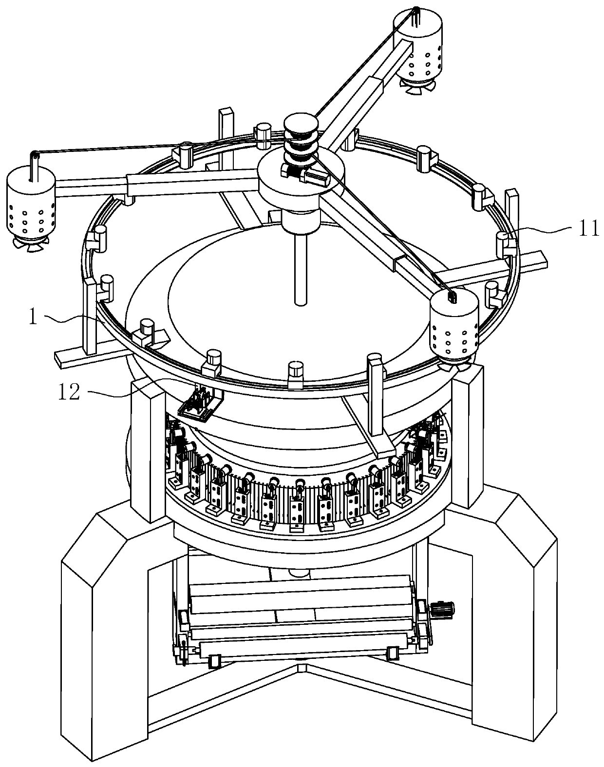
[0042] refer to figure 1 , a yarn tensioning device for a circular knitting machine, comprising a frame 1 on which a plurality of yarn storage devices 11 are fixedly arranged, and a horizontal plate 12 is fixedly installed on the frame 1 and below the yarn storage devices 11.

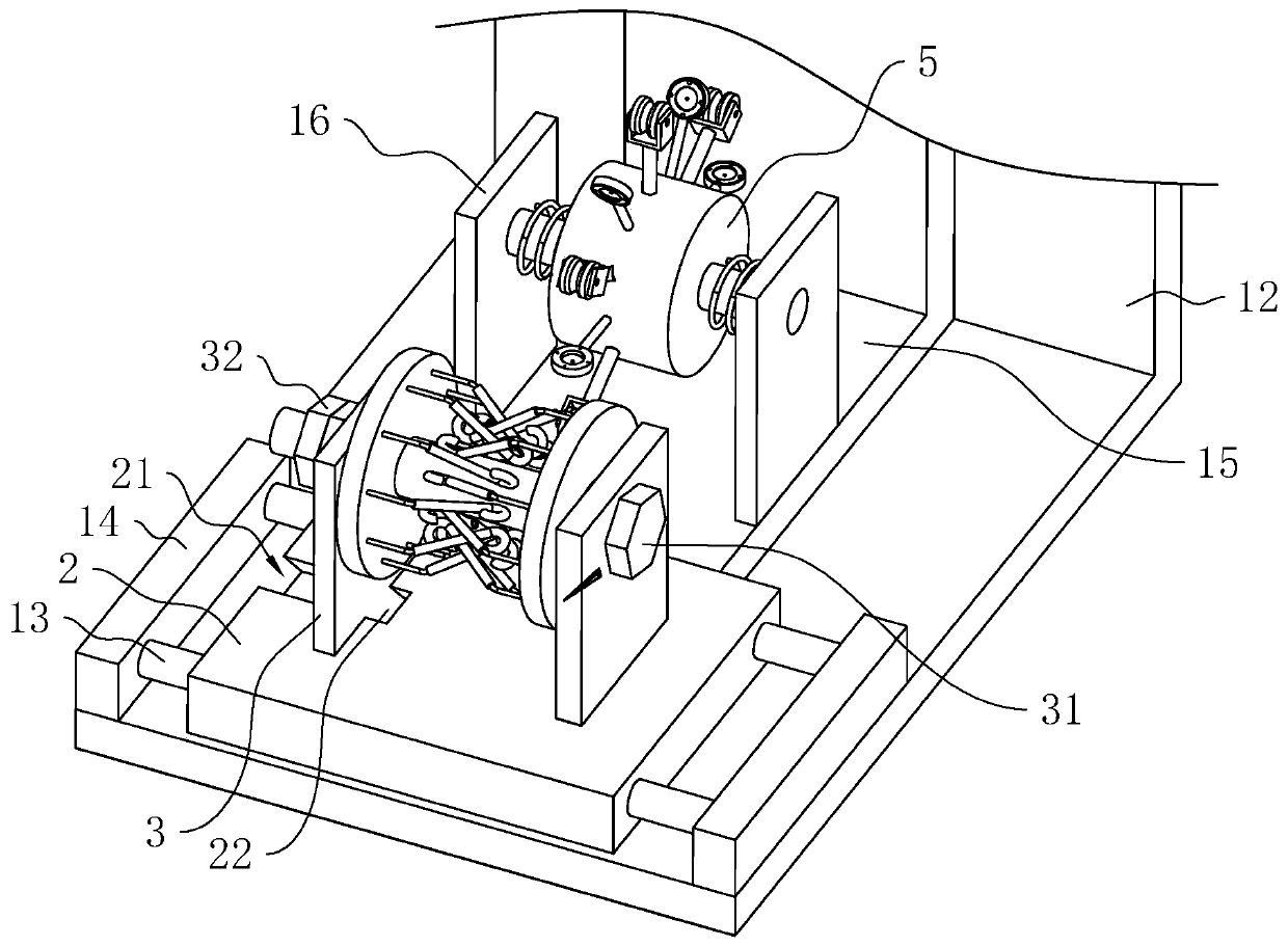
[0043] refer to figure 1 and figure 2 , the upper surface of the horizontal plate 12 is sequentially provided with a fixed frame 2 and a mounting frame 15 from the end far away from the yarn storage device 11 to the end close to the yarn storage device 11, and the yarn passes through the fixed frame 2, the mounting frame 15, and the yarn storage device from the yarn drum 11 enters on the frame 1 and carries out weaving.

[0044] refer to figure 2 , the upper surface of the horizontal plate 12 away from the end of the yarn storage device 11 is fixedly provided with a plurality of ...


PUM


Abstract

The invention relates to a yarn tensioning device of a circular knitting machine, and relates to the technical field of circular knitting machines. The yarn tensioning device comprises a rack, whereina mounting rack and a fixing rack are arranged on the rack; two fixing rings which are oppositely arranged are rotatably mounted on the fixing rack; bent elastic rods are arranged on the two fixing rings in the circumferential direction and in the direction of the opposite sides; the angle of two bent edges of each elastic rod is an obtuse angle; the elastic rods are bent towards the central axesof the fixing rings; the elastic rods on the two fixing rings are arranged in a staggered manner, and an annular area is formed in the staggered position; a fixing ring is arranged on the mounting rack; a rubber sheet is arranged on the fixing ring; a through hole is formed in the rubber sheet; yarn firstly bypass the annular area, then penetrate through the through hole and enter a yarn storagedevice; and the aperture of the through hole is smaller than the diameter of the yarn. According to the yarn tensioning device disclosed by the invention, the yarn are tensioned through the elastic restoring force of the elastic rods and the rubber sheet, so that the yarn can be tightly wound on a yarn conveying wheel, the probability of slipping is greatly reduced, the probability of missing knitting is reduced, and the knitting quality of fabric is greatly improved.

Description

technical field [0001] The invention relates to the technical field of large circular knitting machines, in particular to a yarn tensioning device for large circular knitting machines. Background technique [0002] Circular knitting machine is a kind of textile equipment that uses knitting needles to hook various raw materials and varieties of yarn into loops, and then connects them into knitted fabrics through stringing. The pay-off frame is used to unwind the bobbin yarn, and the unrolled yarn is sent to the knitting mechanism through the yarn feeder for weaving, so the yarn feeder is a very important part of the circular knitting machine. [0003] At present, the Chinese utility model with the authorized notification number CN206476592U discloses a yarn feeder with adjustable yarn distance, which includes a main seat, and the main seat is provided with a yarn presser and a yarn delivery wheel according to the yarn running route. It also includes a mounting plate indirect...

Claims


Application Information

Patent Timeline
Patent Type & Authority Applications(China)
IPC IPC(8): D04B15/44
CPCD04B15/44
Inventor 林龙卿林龙福
Owner 浙江帅龙针织有限公司
Why Eureka
Try Eureka