360-degree rotating chute used for open caisson concrete pouring

A concrete and chute technology, applied in construction, water conservancy projects, artificial islands, etc., can solve the problems of long pouring construction period, high pouring cost, limited construction area, etc. Effect

Inactive Publication Date: 2020-04-17
SINOHYDRO BUREAU 6 CO LTD
View PDF3 Cites 1 Cited by
  • Summary
  • Abstract
  • Description
  • Claims
  • Application Information

AI Technical Summary

Problems solved by technology

[0004] The purpose of the present invention is: in order to solve the problems of the traditional spiral chute for pouring sewage interception pipe network, the construction area is limited, the construction period is longer and the cost of pouring is higher, and a kind of caisson concrete pouring method is proposed. 360 degree rotating chute

Method used


Image

  • 360-degree rotating chute used for open caisson concrete pouring
  • 360-degree rotating chute used for open caisson concrete pouring
  • 360-degree rotating chute used for open caisson concrete pouring

Examples


Embodiment 1

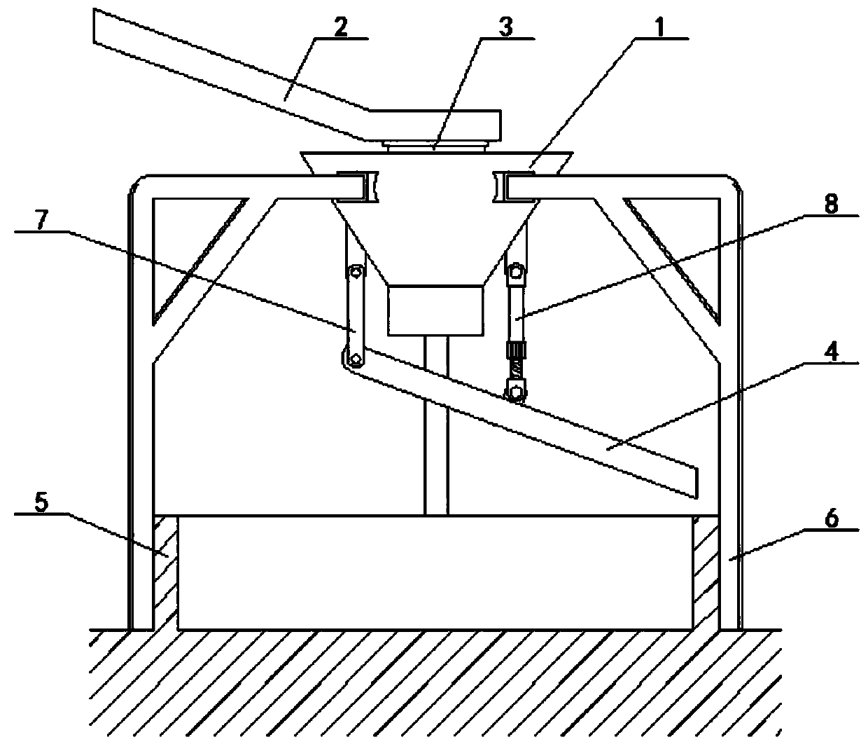
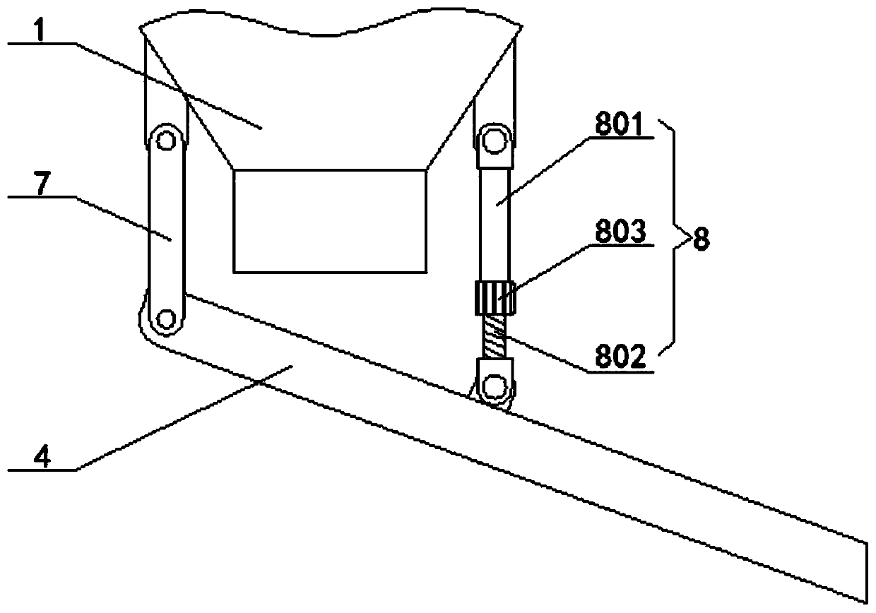
[0026] see Figure 1-3 , the present invention provides a technical solution: a 360-degree rotating chute for caisson concrete pouring, including a hopper 1, an upper chute 2, a lower chute 4 and a well wall 5 to be poured, and a hopper is arranged on the top of the well wall 5 to be poured 1. A rotatable upper chute 2 is installed on the top of hopper 1. The bottom of hopper 1 rotates on the left side and is connected with a connecting rod 7. The bottom end of connecting rod 7 rotates and connects to the lower chute 4. The bottom of hopper 1 rotates on the right side. An adjustable telescopic rod 8 is connected, and the bottom end of the adjustable telescopic rod 8 is rotationally connected with the lower chute 4 .

Embodiment 2

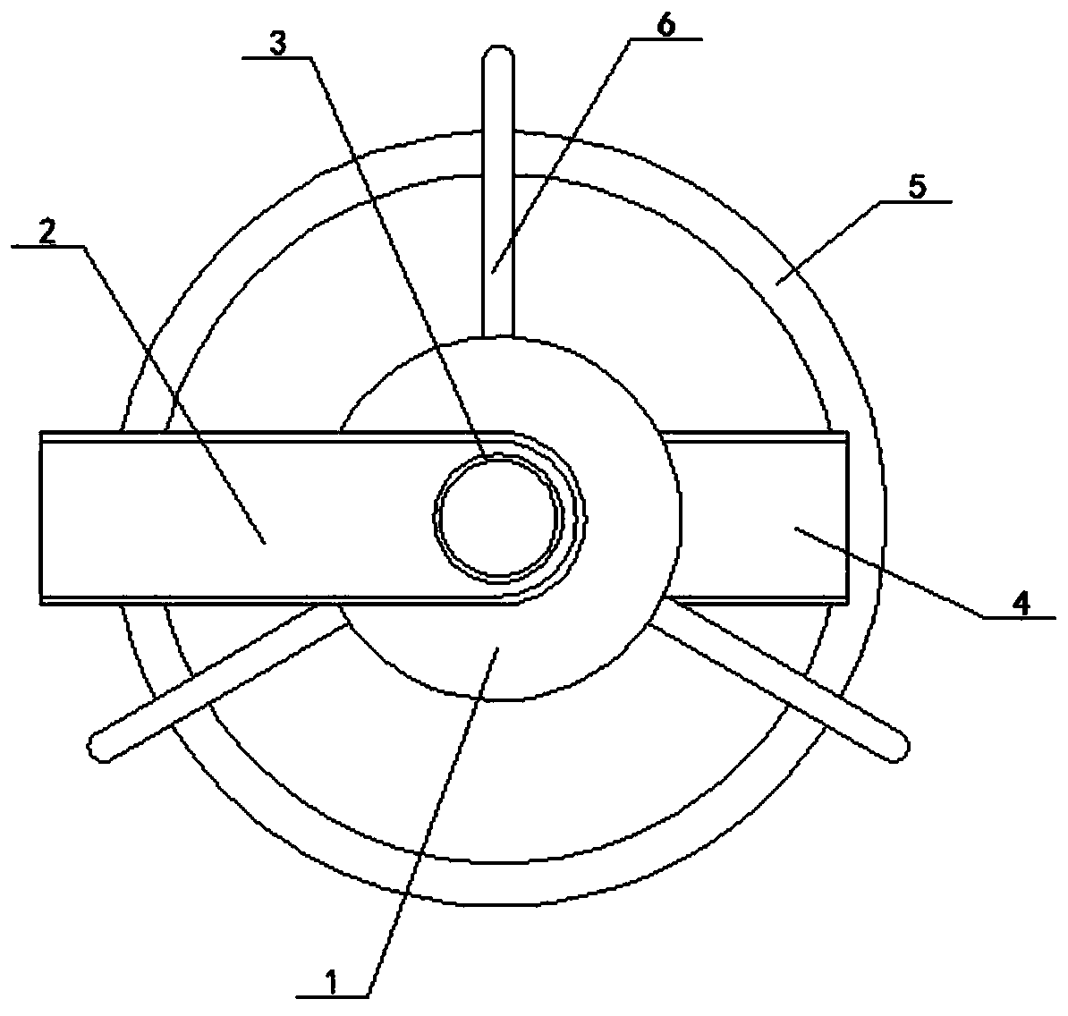
[0028] Specifically, such as figure 1 and figure 2 As shown, the middle part of the upper end surface of the hopper 1 is connected with a vertically distributed feeding pipe 3, and a bearing sleeve is installed between the feeding pipe 3 and the upper chute 2, and the outside of the hopper 1 is equipped with multiple sets of fixed scaffolds distributed in a circular array. 6, and multiple sets of fixed scaffolding 6 are in an inverted L-shaped structure, the upper chute 2 and the lower chute 4 are distributed obliquely, and the setting of the feeding pipe 3 facilitates the flow of concrete from the upper chute 2 into the hopper 1, which is an inverted L-shaped structure The setting of the fixed scaffold 6 facilitates the installation and handling of the bracket of the hopper 1.

Embodiment 3

[0030] Specifically, such as figure 1 and image 3 As shown, the adjustable telescopic rod 8 is composed of an outer tube 801, a screw rod 802 and a screw sleeve 803, the inner side of the bottom end of the outer tube 801 is embedded with a screw rod 802, and the bottom end of the outer tube 801 is located at the outer side of the screw rod 802 and is connected with a screw rod. The sleeve 803, the outer tube 801 and the screw 802 form a transition fit. The selection of the transition fit improves the stability of the screw 802 sliding inside the outer tube 801. The setting of the screw sleeve 803 facilitates the sliding adjustment process of the screw 802 inside the outer tube 801.

[0031] Working principle: When in use, according to the pouring requirements of the municipal sewage interception pipe network, select a fixed scaffold 6 of a specified size to install and erect the hopper 1 above the well wall 5 to be poured, according to the diameter of the well wall 5 to be po...


PUM


Abstract

The invention discloses a 360-degree rotating chute used for open caisson concrete pouring. The 360-degree rotating chute comprises a hopper, an upper chute, a lower chute and a well wall to be poured, the hopper is arranged at the top of the well wall to be poured, the rotary-type upper chute is installed at the top of the hopper, the left side of the bottom of the hopper is rotationally connected with a connecting rotating rod, the bottom end of the connecting rotating rod is rotationally connected with the lower chute, the right side of the bottom of the hopper is rotationally connected with an adjustable telescopic rod, and the bottom end of the adjustable telescopic rod is rotationally connected with the lower chute. According to the 360-degree rotating chute used for open caisson concrete pouring, firstly, the flow speed of concrete can be reduced, so that the concrete is stably warehoused at a constant speed, the pouring quality of the concrete is better guaranteed; secondly, the safety risk that the chutes are not firmly fixed again due to multiple times of movement or re-adjustment is reduced, so that the probability of chute dumping accidents is effectively controlled, and the construction safety is guaranteed; and finally, the phenomena of concrete scattering and leakage in the pouring process are reduced, and the problem that the segregation phenomenon caused by direct warehousing of the concrete occurs is avoided.

Description

technical field [0001] The invention relates to the technical field of pouring equipment for municipal sewage interception pipe networks, in particular to a 360-degree rotating chute for caisson concrete pouring. Background technique [0002] Municipal engineering refers to the construction of municipal facilities. In my country, municipal facilities refer to various buildings, structures, equipment, etc. that are set up within the planning and construction scope of urban areas, towns (townships), and provide residents with paid or unpaid public products and services based on government responsibilities and obligations. The construction of various public infrastructure supporting urban life belongs to the category of municipal engineering, such as common urban roads, bridges, subways, such as various pipelines closely related to life: rainwater, sewage, water supply, reclaimed water, electricity (outside the red line) Partial), telecommunications, heat, gas, etc., as well a...

Claims


Application Information

Patent Timeline
Patent Type & Authority Applications(China)
IPC IPC(8): E02D15/02E02D29/045
CPCE02D15/02E02D29/045
Inventor 郭帅吴华北赵守常白杨
Owner SINOHYDRO BUREAU 6 CO LTD
Why Eureka
Try Eureka