Turbine blade tailing edge curved type exhaust crack structure

A turbine blade and trailing edge technology, applied in the directions of blade support elements, engine elements, machines/engines, etc., can solve the problems of blade structural strength damage, large flow resistance, low cooling effect, etc., to improve efficiency and reduce flow Resistance and loss, the effect of reducing cold air flow resistance and loss

Active Publication Date: 2020-04-17
DALIAN UNIV OF TECH
View PDF17 Cites 6 Cited by
  • Summary
  • Abstract
  • Description
  • Claims
  • Application Information

AI Technical Summary

Problems solved by technology

This kind of trailing edge slit cooling structure has greater flow resistance and lowe

Method used


Image

  • Turbine blade tailing edge curved type exhaust crack structure
  • Turbine blade tailing edge curved type exhaust crack structure
  • Turbine blade tailing edge curved type exhaust crack structure

Examples


Embodiment 1

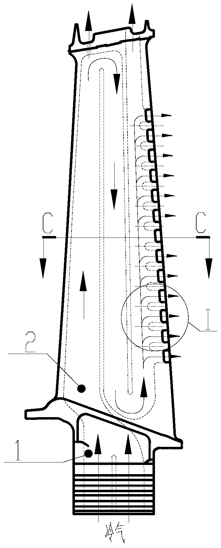
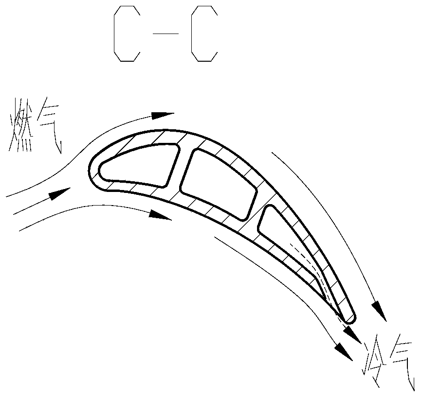
[0036] Please refer to Figure 2. A turbine blade trailing edge curved exhaust splitting structure, comprising a hollow turbine blade 1, an inner cavity cold air channel 2, a trailing edge exhaust splitting channel 3 and a trailing edge splitting rib 4;

[0037] The hollow turbine blade 1 is provided with an inner cavity cold air channel 2 for low-temperature cooling gas to flow inside the blade to cool the blade. The trailing edge of the hollow turbine blade 1 is provided with trailing edge slit ribs 4 arranged side by side, and a trailing edge exhaust slit channel 3 is formed between the trailing edge slit ribs 4 arranged side by side, for the cooling air to discharge the blade, and at the same time The trailing edge of the blade is cooled by film blanket. In addition to increasing the internal heat exchange area of ​​the blade, the structure of the split rib 4 at the trailing edge also guides the cooling air in the inner cavity of the blade so that its flow direction turns....

Embodiment 2

[0040] Please refer to Figure 2. A turbine blade trailing edge curved exhaust splitting structure, comprising a hollow turbine blade 1, an inner cavity cold air channel 2, a trailing edge exhaust splitting channel 3 and a trailing edge splitting rib 4;

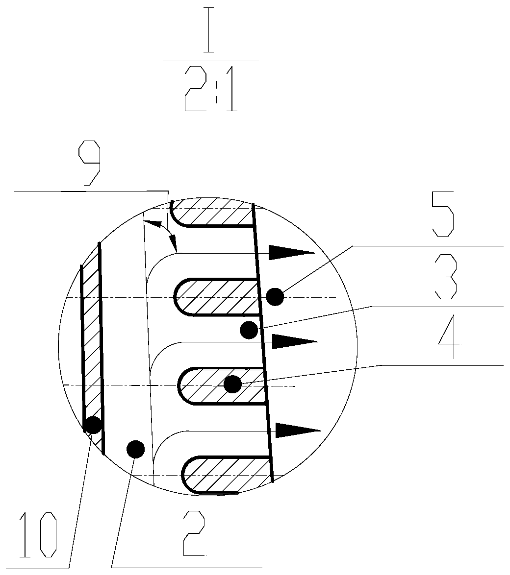
[0041] The structural shape of the split rib 4 at the trailing edge is controlled by the center line 5 of the rib. The center line 5 of the rib is an arc or a spline curve, and the split rib 4 at the trailing edge forms an arc or a spline curve. The width of the split rib 4 at the trailing edge is symmetrically distributed along the center line 5 of the rib. The angles between the tangent direction and the horizontal plane of the trailing edge exhaust slit centerline 6 at the cold air inlet and outlet ends of the hollow turbine blade 1 are the incident angle ∠A1 and the outgoing angle ∠A2, and ∠A1>∠A2. Typical values ​​are ∠A1 = 15° and ∠A2 = 0°, at this time, the air-conditioning turning angle ∠A is about 75°.

Embodiment 3

[0043] Please refer to Figure 2. A turbine blade trailing edge curved exhaust splitting structure, comprising a hollow turbine blade 1, an inner cavity cold air channel 2, a trailing edge exhaust splitting channel 3 and a trailing edge splitting rib 4;

[0044] The structural shape of the split rib 4 at the trailing edge is controlled by the center line 5 of the rib. The center line 5 of the rib is an arc or a spline curve, and the split rib 4 at the trailing edge forms an arc or a spline curve. The width of the split rib 4 at the trailing edge is symmetrically distributed along the center line 5 of the rib. The angles between the tangent direction and the horizontal plane of the trailing edge exhaust slit centerline 6 at the cold air inlet and outlet ends of the hollow turbine blade 1 are the incident angle ∠A1 and the outgoing angle ∠A2, and ∠A1>∠A2. Typical values ​​can be ∠A1=25° and ∠A2=15°, and the turning angle of the cold air ∠A is about 65°.


PUM


Abstract

The invention belongs to the technical field of cooling of aero-engine turbines, and relates to a turbine blade tailing edge curved type exhaust crack structure. The curved type exhaust crack structure comprises hollow turbine blades, inner cavity cold air channels, tailing edge exhaust crack channels and tailing edge crack partition ribs. The inner cavity cold air channels are formed in the hollow turbine blades so that low-temperature cooling air can flow in the blades and cool the blades. The tailing edge crack partition ribs arrayed side by side are arranged on the tailing edges of the hollow turbine blades. The tailing edge exhaust crack channels are formed between the tailing edge crack partition ribs arrayed side by side so that cooling air can be discharged out of the blades. Bladetailing edge cracks are designed to have an inclined curved type exhausting function, the turning angle of the cooling air in the cracks is reduced, the turning process is continuous and gentle, andtherefore the flowing resistance and loss of the cooling air in inner cavities of the blades are reduced, and the flowing resistance can be reduced by about 20%.

Description

technical field [0001] The invention belongs to the technical field of aero-engine turbine cooling, and relates to a curved exhaust slit structure at the trailing edge of a turbine blade. Background technique [0002] Increasing the gas temperature before the turbine can greatly improve the efficiency of aero-engines and gas turbines, but the current gas temperature before the turbine has far exceeded the limit of the materials used, so it is urgent to develop more effective turbine blade cooling technology. At present, the hollow design is generally adopted for the turbine blades, and the heat is taken away by the enhanced convection heat transfer of the cooling gas inside and the air film is formed to cover and isolate the gas heating when the blades are discharged. This is the main solution to the cooling problem of the turbine blades. Larger internal heat exchange area", "smaller cold air flow resistance", "higher heat exchange efficiency", "larger air film coverage area...

Claims


Application Information

Patent Timeline
IPC IPC(8): F01D5/18
CPCF01D5/186
Inventor 吕东孔星傲王晓放王楠孙一楠
Owner DALIAN UNIV OF TECH
Why Eureka
Try Eureka