Interlock pneumatic control system of de-slagging gate

The technology of a pneumatic control system and a slag discharge door is applied to door/window fittings, fluid pressure actuating devices, switches with brake parts, etc. To achieve the effect of simple operation, convenient operation, safety and reliability, and reasonable structure setting

Active Publication Date: 2020-04-17
浙江天联机械有限公司
View PDF12 Cites 0 Cited by
  • Summary
  • Abstract
  • Description
  • Claims
  • Application Information

AI Technical Summary

Problems solved by technology

That is to say, the operation sequence is unlocking-opening-closing-locking, and there should be no action that violates the operation sequence

Method used


Image

  • Interlock pneumatic control system of de-slagging gate
  • Interlock pneumatic control system of de-slagging gate
  • Interlock pneumatic control system of de-slagging gate

Examples


Embodiment Construction

[0031] In the description of this embodiment, it should be noted that if the terms "center", "upper", "lower", "left", "right", "vertical", "horizontal", "inner", " Outside", "front", "rear", etc., the orientation or positional relationship indicated is based on the orientation or positional relationship shown in the drawings, which is only for the convenience of describing the present invention and simplifying the description, rather than indicating or implying Any device or element must have a specific orientation, be constructed and operate in a specific orientation and, therefore, should not be construed as limiting the invention. In addition, the terms "first", "second", and "third" are used for descriptive purposes only, and should not be understood as indicating or implying relative importance.

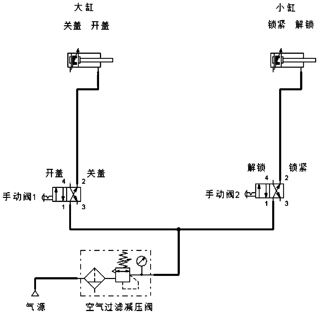
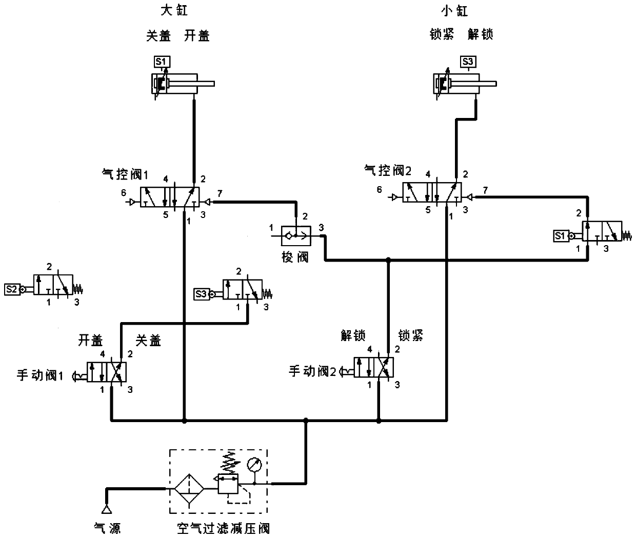
[0032] see Figure 2 to Figure 4 , a slag door interlocking pneumatic control system disclosed in the present invention includes an air source and a cylinder, and also include...


PUM


Abstract

The invention discloses an interlock pneumatic control system of a de-slagging gate. The system comprises a gas source and a gas cylinder and also comprises a first pneumatic control valve, a second pneumatic control valve, a first manual valve, a second manual valve, a first stroke switch, a second stroke switch, a third stroke switch, a tee connector and a shuttle valve. The technical solution has the beneficial effects that at positions of cover closing and locking, a function of manual cover opening fails, and two channels of mechanical stroke switch gas valves are adopted, so two-channelgas signals of the first pneumatic control valve can be cut off at the same time; when the air cylinder is moved to an unlocking position, the two-channel mechanical stroke switch gas signals can be triggered at the same time, and only one channel can be used normally; because of the stroke switches and a locking gas loop, a unique gas signal loop for cover closing can be ensured by the shuttle valve; and actions of the air cylinder can be switched by the first pneumatic control valve and the second pneumatic control valve based on pneumatic signals, and the air cylinder at the cover closing position triggers the first stroke switch, so the second manual valve can send a pneumatic signal to the second pneumatic control valve for switching of a locking action and an unlocking action; and structural design is reliable, an operation sequence is unique, and operations are convenient, safe and reliable.

Description

technical field [0001] The invention relates to the technical field of mechanical equipment, in particular to a slag door interlocking pneumatic control system. Background technique [0002] Existing slag door device is made up of two parts of door cover and rotation lock, and the door cover and rotation lock of drive device are respectively driven by two groups of cylinders. Rotation lock is a safety device to prevent accidents and material loss caused by accidental opening of the door cover. When the equipment is in normal process, the reciprocating action of the cylinder is completed through the manual control valve, see figure 1 , The manual valve 1 has the state of opening and closing the cover, and the manual valve 2 has the state of unlocking and locking. First, the manual valve 2 is unlocked, the revolving door is opened, and then the cover is opened by the manual valve 1, and the cover door is opened. Carry out the waste slag cleaning in the tank body, after proc...

Claims


Application Information

Patent Timeline
IPC IPC(8): F15B11/06F15B11/20F15B13/07E05F3/02E05F17/00
CPCE05F3/02E05F17/00F15B11/06F15B11/20F15B13/07
Inventor 沈永华沈铭隆项光云季永早项鹏豪季温特吴国雄张圣洁
Owner 浙江天联机械有限公司
Why Eureka
Try Eureka