
Lubricating device of self-lubricating sliding bearing

A sliding bearing and lubricating device technology, applied in sliding contact bearings, engine lubrication, lubrication pumps, etc., can solve problems such as increased use costs, reduced control logic, and alloy wear on the surface of sliding bearings.

Pending Publication Date: 2020-04-17
JIAMUSI ELECTRIC MACHINE
View PDF0 Cites 2 Cited by
  • Summary
  • Abstract
  • Description
  • Claims
  • Application Information

AI Technical Summary

Problems solved by technology

Sliding bearings are divided into self-lubricating and forced-lubricating if they are distinguished according to their lubrication methods; the sliding bearings with forced lubrication need to have lubricating oil flowing before the motor starts and during operation, so as to ensure that there is enough lubricating oil between the shaft and the motor when starting. The bearing temperature is lowered between the bearings at the same time, but this kind of lubrication method requires a separate lubricating oil station to supply oil to the bearings, which not only increases the cost of use, but also consumes a lot of electric energy. For occasions where the bearing temperature is not high during operation, if It is possible to keep enough lubricating oil on the shaft and the sliding bearing bracket before starting, so that the lubricating oil station can no longer be used, thus saving costs and reducing the control logic in actual use
[0003] In the prior art, there is no lubricating oil between the shaft and the sliding bearing after being placed for a long time, resulting in the wear of the alloy on the surface of the sliding bearing during the starting process

Method used


Image

  • Lubricating device of self-lubricating sliding bearing

Examples


Embodiment Construction

[0013] The present invention will be described in further detail below in conjunction with the accompanying drawings: the present embodiment is implemented on the premise of the technical solution of the present invention, and detailed implementation is provided, but the protection scope of the present invention is not limited to the following embodiments.

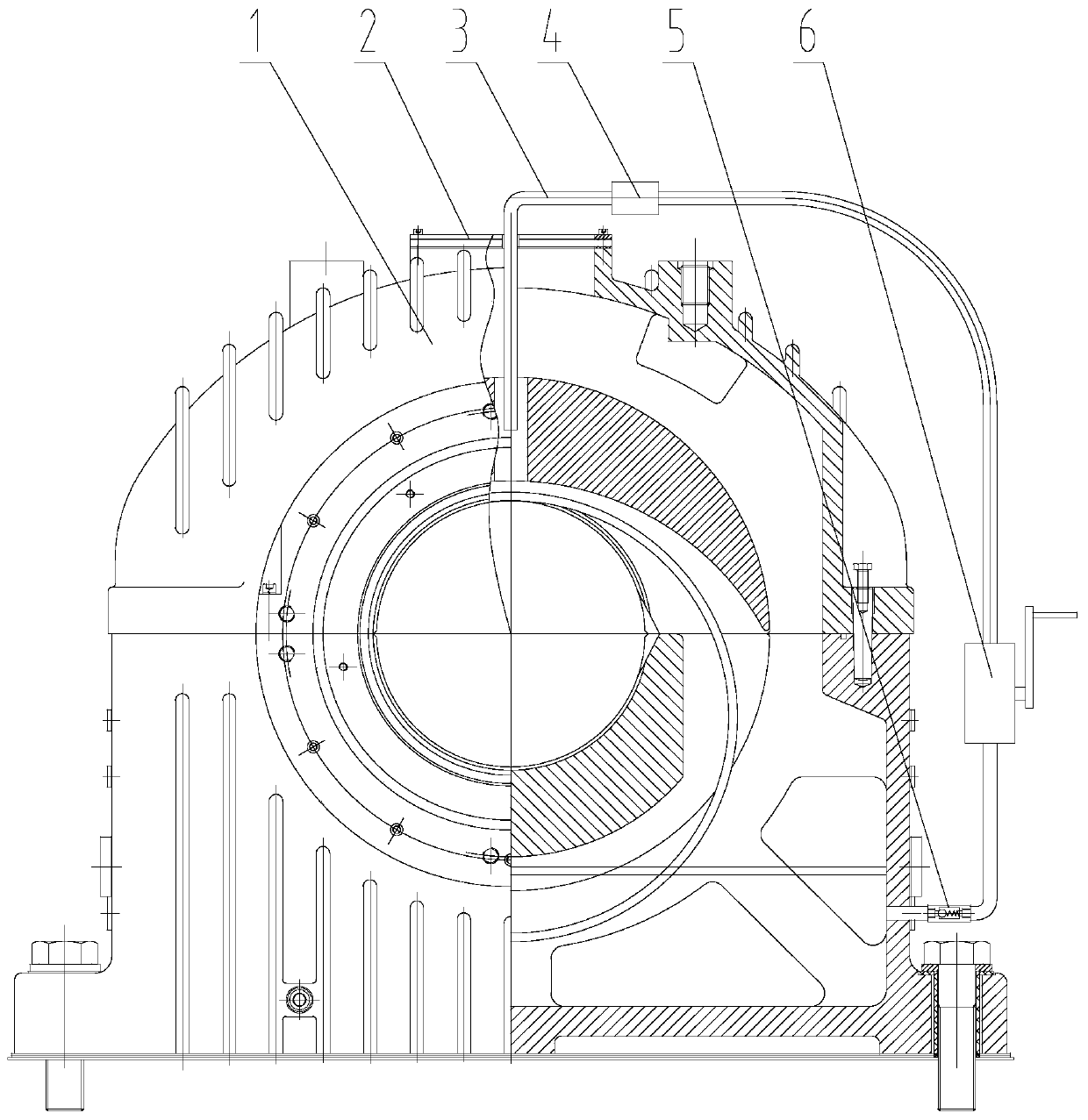
[0014] Such as figure 1 As shown, a lubricating device for a self-lubricating sliding bearing involved in this embodiment includes: a sliding bearing body 1, a transparent sealing cover plate 2, an oil inlet pipe 3, a sight glass 4, a one-way valve 5 and a pump 6, and the transparent sealing The cover plate 2 has a threaded hole for installing the oil inlet pipe 3 and is installed on the top of the sliding bearing body 1 as a whole. The sight glass 4 is installed in the oil inlet pipe 3 to check whether there is lubricating oil flowing during the oil filling process. Check valve 5 is installed at the oil outlet of the bear...


PUM


Abstract

The invention provides a lubricating device of a self-lubricating sliding bearing, and belongs to the technical field of bearing lubricating devices. The lubricating device comprises a sliding bearingbody, a transparent sealing cover plate, an oil inlet pipe, sight glass, a one-way valve and a pump. The transparent sealing cover plate is provided with a threaded hole used for mounting the oil inlet pipe and integrally arranged above the sliding bearing body; the sight glass is arranged in the oil inlet pipe; the one-way valve is arranged at the position of a bearing bush oil outlet of the sliding bearing body, and the pump is connected to the oil inlet pipe between the sight glass and the one-way valve in series. The oil pump is arranged on the outer side of the sliding bearing, lubricating oil in the sliding bearing is pumped out from the lower part of the bearing seat through the micro-backpressure one-way valve; the lubricating oil enters the space between a shaft and a bearing from the top of the sliding bearing, the transparent sight glass is arranged on a pipeline before the lubricating oil enters the bearing, observation can be conducted through observation of the sight glass, it is guaranteed that enough lubricating oil flows into the sliding bearing, formation of an oil film is facilitated, and abrasion between a bearing bush and the shaft is reduced.

Description

technical field [0001] The invention relates to a lubricating device for a self-lubricating sliding bearing, which belongs to the technical field of bearing lubricating devices. Background technique [0002] Sliding bearings are widely used for their long life, high speed, shock and vibration load and low noise. Sliding bearings are divided into self-lubricating and forced-lubricating if they are distinguished according to their lubrication methods; the sliding bearings with forced lubrication need to have lubricating oil flowing before the motor starts and during operation, so as to ensure that there is enough lubricating oil between the shaft and the motor when starting. The bearing temperature is lowered between the bearings at the same time, but this kind of lubrication method requires a separate lubricating oil station to supply oil to the bearings, which not only increases the cost of use, but also consumes a lot of electric energy. For occasions where the bearing temp...

Claims


Application Information

Patent Timeline
IPC IPC(8): F16C25/04F16C33/10F16N13/00F16N23/00
CPCF16C25/04F16C33/1025F16C33/1045F16N13/00F16N23/00
Inventor 历锐姜巍苏国霞王洪彬马文博李方华姜海艳王红金樊明原朱孟华
Owner JIAMUSI ELECTRIC MACHINE
Learn More