Passive house system

A passive house and system power supply technology, which is applied in the field of passive house systems, can solve the problems of high power of air-conditioning equipment, and achieve the effects of energy saving, high comfort and small space occupation

Pending Publication Date: 2020-04-17
GREE ELECTRIC APPLIANCES INC
View PDF0 Cites 4 Cited by
  • Summary
  • Abstract
  • Description
  • Claims
  • Application Information

AI Technical Summary

Problems solved by technology

[0004] The main purpose of the present invention is to provide a passive house system to solve the problem of high power of the air conditioner used in the passive house system in the prior art

Method used


Image

  • Passive house system

Examples


Embodiment Construction

[0020] The following will clearly and completely describe the technical solutions in the embodiments of the present invention with reference to the accompanying drawings in the embodiments of the present invention. Obviously, the described embodiments are only some of the embodiments of the present invention, not all of them. The following description of at least one exemplary embodiment is merely illustrative in nature and in no way taken as limiting the invention, its application or uses. Based on the embodiments of the present invention, all other embodiments obtained by persons of ordinary skill in the art without creative efforts fall within the protection scope of the present invention.

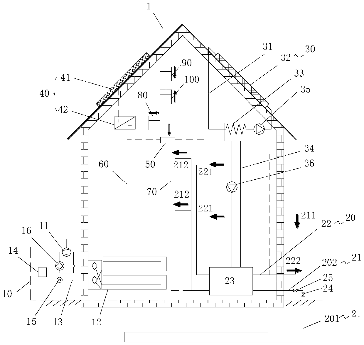
[0021] In order to solve the problem of high power of the air conditioner used in the passive house system in the prior art, the present invention provides a passive house system.

[0022] Such as figure 1 As shown, the passive house system includes an air conditioner 10, the air condi...


PUM


Abstract

The invention provides a passive house system. The passive house system comprises air-conditioning equipment, wherein the air-conditioning equipment comprises a compressor and an indoor heat exchanger; the compressor is connected to the indoor heat exchanger; the indoor heat exchanger is a radiant type heat exchanger; the radiant type heat exchanger is laid on the ground or wall space or a top plate; and the power of the compressor is 300W to 2000W. The technical solution of the passive house system solves the problem that the air-conditioning equipment used in the passive house system in theprior art has relatively high power.

Description

technical field [0001] The invention relates to the technical field of energy-saving buildings, in particular to a passive house system. Background technique [0002] Passive house is a new energy-saving building. It consumes less primary energy by adopting high heat insulation and sound insulation, strong airtight building exterior walls and making full use of renewable energy. [0003] Since the annual heat consumption for heating and cooling of a passive house is smaller than that of a conventional building, the air conditioning equipment used in the existing passive house system has a higher power. For example, the minimum starting power of multi-connected equipment is about 8kW, while the actual power demand of each household in a passive house is usually lower than 2kW, which will cause a lot of waste, and the existing passive house system uses indoor heat exchangers in air-conditioning equipment There are disadvantages such as large volume and poor comfort. Content...

Claims


Application Information

Patent Timeline
Patent Type & Authority Applications(China)
IPC IPC(8): F24F1/0003F24F1/0063F24F13/30F24F5/00F24F7/04F24F12/00F24F13/02F24F11/89H02J3/38H02J7/35H02J9/06
CPCF24F1/0003F24F1/0063F24F5/001F24F5/0046F24F7/04F24F11/89F24F12/001F24F13/02F24F13/30F24F2005/0057F24F2005/0064F24F2005/0067H02J7/35H02J9/062Y02A30/00Y02B10/40Y02B10/70Y02B30/90
Inventor 谢文利黄玉优王子平
Owner GREE ELECTRIC APPLIANCES INC
Why Eureka
Try Eureka