Electronic detonator chip leg wire riveting device and processing flow based on same

An electronic detonator and riveting device technology, applied in weapon accessories, fuzes, offensive equipment, etc., can solve the problems of high labor intensity, operators are vulnerable to mechanical damage, low production efficiency, etc., to reduce labor intensity and improve equipment production. Efficiency, cost reduction effect

Pending Publication Date: 2020-04-17
杭州晋旗电子科技有限公司
View PDF0 Cites 3 Cited by
  • Summary
  • Abstract
  • Description
  • Claims
  • Application Information

AI Technical Summary

Problems solved by technology

[0002] In the field of electronic detonator production, the riveting method of the electronic detonator chip and the foot wire is manual work. First, the exposed wires at the front end of the electronic detonator chip and the foot wire sealing match are butted on the hand, and then they are taken together to the positioning mold of the riveting tooling. Riveting; the production efficiency of such riveting method is low, the labor intensity of personnel is high, and the operators are vulnerable to mechanical damage, which is not conducive to the automatic production of electronic detonators in large quantities. device and its processing flow to solve the above problems

Method used


Image

  • Electronic detonator chip leg wire riveting device and processing flow based on same
  • Electronic detonator chip leg wire riveting device and processing flow based on same
  • Electronic detonator chip leg wire riveting device and processing flow based on same

Examples


Embodiment 1

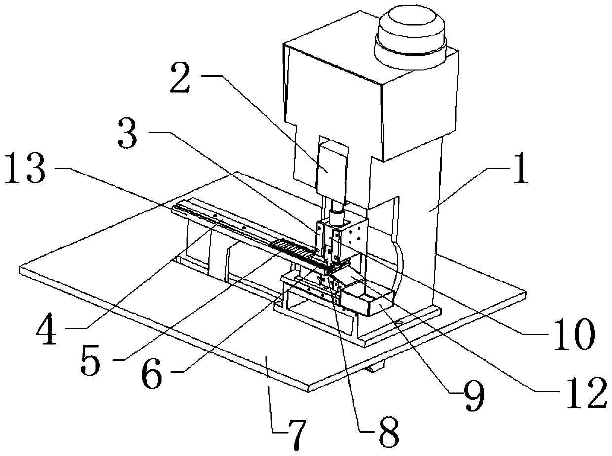
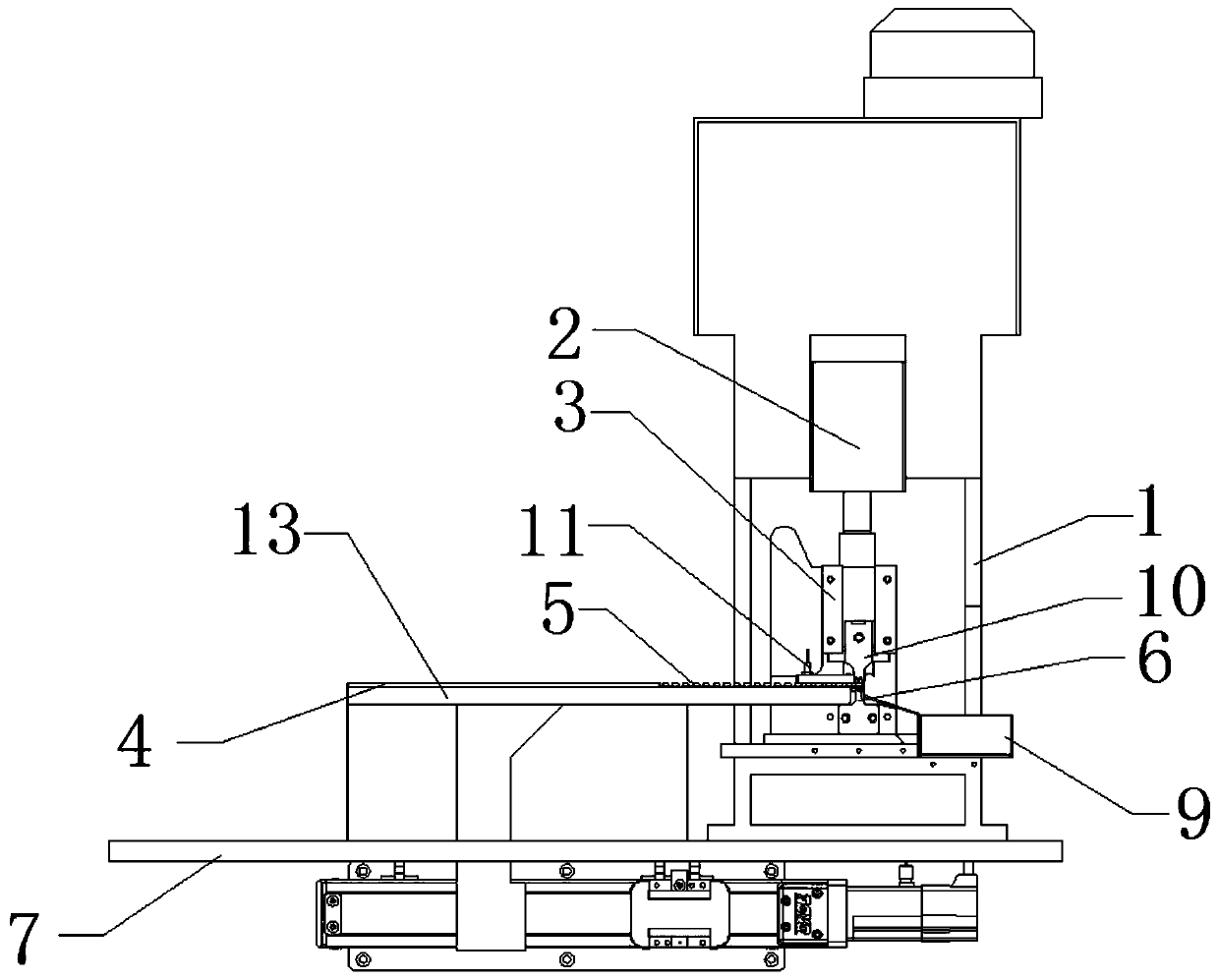
[0027] see Figure 1-5 , the present invention provides a technical solution: a leg riveting device for an electronic detonator chip, including a terminal machine 1, an output shaft 2 of the terminal machine, a slide rail 3, a stepping feeding mechanism 4, an upper riveting knife 6, a chassis 7, Lower riveting knife 8, slide block 10 and guide rail 13, described terminal machine 1 and guide rail 13 are all arranged on the chassis 7, described guide rail 13 is provided with step feeding mechanism 4, and the output shaft 2 of described terminal machine is arranged on The inner top of the terminal machine 1. The slide rail 3 is fixed inside the terminal machine 1 and is located on the lower side of the output shaft 2 of the terminal machine. The slider 10 is slidably connected to the inside of the slide rail 3. The output shaft 2 of the terminal machine is fixedly connected, the upper riveting knife 6 is fixedly arranged on the side of the slider 10 away from the output shaft 2 o...

Embodiment 2

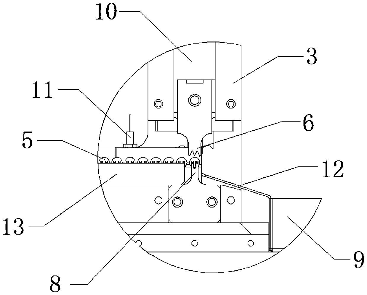
[0031] As a preferred solution of Embodiment 1, a detection mechanism 11 is also included, and the detection mechanism 11 includes an electronic detonator chip detector, a recovery box 9 and a slant plate 12, and the electronic detonator chip detector is arranged on the slide rail on the terminal machine 1 3 On the side close to the guide rail 13, the recovery box 9 is set on the terminal machine 1, and is located on the side of the lower riveting knife 8 away from the guide rail 13, between the end of the guide rail 13 close to the upper riveting knife 6 and the recovery box 9 A slant plate 12 is provided.


PUM


Abstract

The invention relates to an electronic detonator chip leg wire riveting device and a processing flow based on the same. The device comprises a terminal machine, an output shaft of the terminal machine, a sliding rail, a stepping feeding mechanism, an upper riveting knife, a bottom plate, a lower riveting knife, a recycling box, a sliding block and a guide rail. The flow further comprises the following steps that the stepping feeding mechanism is matched to push a electronic detonator chip to move towards the tail end of the guide rail until the electronic detonator chip is moved to the properposition; the output shaft of the terminal machine drives the sliding block to move downwards in the sliding rail, and the upper riveting knife is driven to move downwards, and is matched with the lower riveting knife to rivet a leg wire and the electronic detonator chip; the electronic detonator chip which is in butt joint with the leg wire is taken down, the above steps are repeated for competing processing on all electronic detonator chips. According to the device, the purpose of automatic feeding of the electronic detonator chips during riveting of the electronic detonator chips and leg wires is achieved, the labor intensity of operators is reduced, and the equipment production efficiency is improved.

Description

technical field [0001] The invention relates to the field of printing equipment, in particular to a leg riveting device for an electronic detonator chip and a processing flow thereof. Background technique [0002] In the field of electronic detonator production, the riveting method of the electronic detonator chip and the foot wire is manual work. First, the exposed wires at the front end of the electronic detonator chip and the foot wire sealing match are butted on the hand, and then they are taken together to the positioning mold of the riveting tooling. Riveting; the production efficiency of such riveting method is low, the labor intensity of personnel is high, and the operators are vulnerable to mechanical damage, which is not conducive to the automatic production of electronic detonators in large quantities. device and its processing flow to solve the above-mentioned problems. Contents of the invention [0003] The purpose of the present invention is to provide a leg...

Claims


Application Information

Patent Timeline
Patent Type & Authority Applications(China)
IPC IPC(8): F42C17/04
CPCF42C17/04
Inventor 李叶磊王斐
Owner 杭州晋旗电子科技有限公司
Why Eureka
Try Eureka