FPGA-based SOC chip automatic test tool and test method

A technology of automated testing and testing tools, applied in the direction of electronic circuit testing, measuring electricity, measuring devices, etc., can solve the problems of cumbersome communication at various baud rates, repeated work, cumbersome plugging and unplugging of connecting wires, etc., to achieve automated testing Effect

Inactive Publication Date: 2020-04-17
中电海康无锡科技有限公司
View PDF7 Cites 7 Cited by
  • Summary
  • Abstract
  • Description
  • Claims
  • Application Information

AI Technical Summary

Problems solved by technology

[0004] (1) When testing the PWM mode of the SOC chip timer (Timer), when the SOC chip outputs PWM signals with different frequencies, duty ratios and whether there is a dead zone, it is necessary to use an oscilloscope or a logic analyzer to continuously capture different frequencies and duty cycles. Duty ratio and PWM waveform with or without dead zone are analyzed, and there is a lot of repetitive work;
[0005] (2) When testing the Compare mode of the SOC chip timer (Timer), when the SOC chip outputs comparison signals of different frequencies and duty ratios, it is necessary to use an oscilloscope or a logic analyzer to continuously capture different frequencies and duty ratios. Comparing waveforms for analysis requires a lot of repetitive work;
[0008] (5) For the test of the SOC chip serial port (UART), the conventional test is to use the serial port debugging assistant, which needs to set the same baud rate for the serial port debugging assistant and the SOC chip, and it is cumbersome to test multiple baud rate communications;
When testing the I2C slave mode, an external I2C master device is required, and it is cumbersome to plug and unplug the connecting wire;
[0011] (8) For the AD module and DA module of the SOC chip, there is still a lack of relevant testing methods

Method used


Image

  • FPGA-based SOC chip automatic test tool and test method
  • FPGA-based SOC chip automatic test tool and test method
  • FPGA-based SOC chip automatic test tool and test method

Examples


Embodiment Construction

[0047] The present invention will be further described below in conjunction with specific drawings and embodiments.

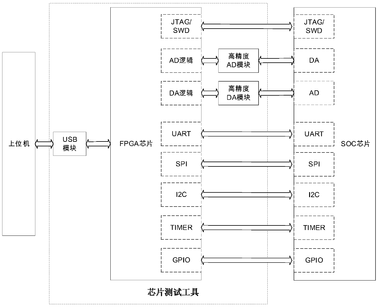
[0048] The embodiment of the present invention proposes an FPGA-based SOC chip automated testing tool, including a connected host computer interface module, an FPGA chip, a high-precision AD module, and a high-precision DA module; the host computer interface module is used to connect the host computer, Specifically, the USB module is used;

[0049] The FPGA chip is provided with:

[0050] The JTAG / SWD logic module is used to connect the JTAG / SWD module on the SOC chip;

[0051] AD logic module, which controls the high-precision AD module to connect with the DA module on the SOC chip;

[0052] DA logic module, which controls the high-precision DA module to connect with the AD module on the SOC chip;

[0053] UART logic serial port module, used to connect to the UART serial port module on the SOC chip;

[0054] The SPI logic module is used to connect the SPI ...


PUM


Abstract

The invention provides an SOC chip automatic test tool based on an FPGA. The SOC chip automatic test tool comprises an upper computer interface module, an FPGA chip, a high-precision AD module and a high-precision DA module which are connected, wherein the upper computer interface module is used for being connected with an upper computer, the FPGA chip is provided with a JTAG/SWD logic module usedfor being in butt joint with a JTAG/SWD module on the SOC chip, an AD logic module used for controlling the high-precision AD module to be in butt joint with the DA module on the SOC chip, the DA logic module used for controlling the high-precision DA module to be in butt joint with the AD module on the SOC chip, an UART logic serial port module used for being in butt joint with a UART serial port module on the SOC chip, an SPI logic module used for being in butt joint with an SPI module on the SOC chip, an I2C logic module used for being in butt joint with an I2C module on the SOC chip, a timer logic module used for verifying a timer on the SOC chip, and a GPIO logic module used for being in butt joint with a GPIO module on the SOC chip. The test tool is advantaged in that full automation of the test process is realized.

Description

technical field [0001] The invention relates to the field of SOC chip testing, in particular to an FPGA-based SOC chip automatic testing tool and testing method. Background technique [0002] At present, in the SOC chip FPGA prototype verification stage, every time the chip design is modified, the FPGA prototype needs to be verified once. Since there are generally many SOC chip peripherals, most of the peripheral tests need to be assisted by oscilloscopes, logic analyzers, and signal generators, and some module tests also need to be connected with Dupont wires. The test work is cumbersome and repetitive, and the test cannot be automatically generated. Report. In view of the above problems, there is an urgent need for a fully automatic SOC chip test platform that can test SOC chips with one key and automatically generate test reports from the test results. [0003] At present, in the field of SOC chip testing, a large number of repetitive work problems caused by the complex...

Claims


Application Information

Patent Timeline
Patent Type & Authority Applications(China)
IPC IPC(8): G01R31/28
CPCG01R31/2851
Inventor 徐金波黄以亮王逸飞徐琴刘新华
Owner 中电海康无锡科技有限公司
Why Eureka
Try Eureka