Separation structure between voltage regulation tapping leads of transformer

A technology for tapping leads and transformers, applied in the directions of transformer/inductor cooling, transformer/inductor housing, etc., can solve the problems of increasing the cross-section of a single lead, increasing the insulation thickness, and increasing the cost of the lead, so as to reduce the design difficulty. , The effect of reducing insulation thickness and size

Pending Publication Date: 2020-04-17
SHANDONG POWER EQUIP
View PDF9 Cites 0 Cited by
  • Summary
  • Abstract
  • Description
  • Claims
  • Application Information

AI Technical Summary

Problems solved by technology

This insulation thickness cannot meet the voltage requirements between the poles of the tap wire. If the insulation thickness of the tap wire continues to increase, the following problems will be caused: 1. Considering the heat dissipation of the lead wire, the insulation thickness increases, resulting in an increase in the selection of the tap wire and increasing the cost of the lead wire; 2. The cross-section of a single lead wire increases, the space occupied by the lead wire increases, and the design difficulty is increased; 3. The insulation thickness and cable cross-section increase, and the lead wire is difficult to bend and clamp, which increases the difficulty of production operation

Method used


Image

  • Separation structure between voltage regulation tapping leads of transformer
  • Separation structure between voltage regulation tapping leads of transformer
  • Separation structure between voltage regulation tapping leads of transformer

Examples


Embodiment Construction

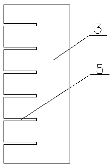
[0024] As shown in the figure, the technical solution of this embodiment is to install insulating pads between the wires in the wire bundle, including the way of installing insulating pads between the wires clamped by the wire clamps and when there are no wires. The method of installing insulating pads between the wires at the clamping place. A wire that is not held by a wire clamp, generally refers to a wire in a wire bundle that is located between two wire clamps.

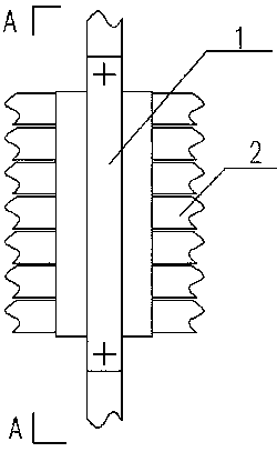
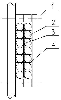
[0025] For the solution at the clamping place of wire clip 1, such as Figure 1-4 shown. It includes a wire clamp 1 and a wire bundle clamped in the wire clamp 1 . The wires 2 in the wire bundle in this embodiment are clamped by the wire clamp 1 into two longitudinal rows, and a longitudinal insulating spacer, that is, a first longitudinal spacer 3, is installed between the two rows of wires, and each row of adjacent wires 2 A horizontal insulating spacer, that is, a first transverse spacer 4, is arranged betw...


PUM

PropertyMeasurementUnit
Thicknessaaaaaaaaaa

Abstract

The invention relates to a separation structure between voltage regulation tapping leads of a transformer, and belongs to the technical field of power transformers. The separation structure comprisesa wire clamp and a wire bundle formed by a group of wires clamped by the wire clamp. The separation structure is characterized in that a longitudinal insulating cushion block for transversely spacingtwo transversely adjacent wires of the wire harness is arranged between the two transversely adjacent wires of the wire harness, a transverse insulating cushion block for longitudinally spacing the two longitudinally adjacent wires is arranged between the two longitudinally adjacent wires of the wire harness, and each insulating cushion block is provided with fixing structures which are arranged between the insulating cushion blocks or between the insulating cushion blocks and the wires. The insulation distance between the tapping leads is increased without increasing the insulation thicknessof the leads. According to the separation structure between the leads, the problem that the potential difference between the adjacent tapping leads is large is effectively solved, the insulation thickness of the leads is reduced, the specification and size of the leads are reduced, and the design cost is reduced; heat dissipation of the tapping leads is facilitated, space occupied by the tapping leads is reduced and design difficulty is reduced.

Description

technical field [0001] The invention relates to a separation structure between voltage-regulating tapping leads of a transformer, and belongs to the technical field of power transformers. Background technique [0002] During the neutral point impact test of the fully insulated transformer tap wire, the potential difference between the head and tail of the tap wire and between the poles is large. When the tap wire is routed, it is necessary to comprehensively consider the insulation distance of the tap wire to the oil tank, coil, etc. and the distance between the tap wires. insulation distance. Due to the high voltage level of the fully insulated transformer tap wire itself, the insulation thickness of the tap wire is selected considering the insulation distance of the tap wire to the fuel tank, coil, etc. This insulation thickness cannot meet the voltage requirements between the poles of the tap wire. If the insulation thickness of the tap wire continues to increase, the fo...

Claims


Application Information

Patent Timeline
IPC IPC(8): H01F27/02H01F27/08
CPCH01F27/02H01F27/08
Inventor 张成飞曹慧敏崔孟凡张凯杨同勋
Owner SHANDONG POWER EQUIP
Why Eureka
Try Eureka