Superconducting cable and DC transmission system incorporating the superconducting cable

a superconducting cable and transmission system technology, applied in the direction of superconducting magnets/coils, magnetic bodies, connection contact material, etc., can solve the problem of excessive temperature rise, achieve the effect of reducing the quantity of superconducting material, reducing flexural rigidity, and forming a convenient twisted structur

Inactive Publication Date: 2010-05-25
SUMITOMO ELECTRIC IND LTD
View PDF10 Cites 4 Cited by
  • Summary
  • Abstract
  • Description
  • Claims
  • Application Information

AI Technical Summary

Benefits of technology

[0077]A superconducting cable of the present invention having the above-described structure achieves the specific effect of easily forming a twisted structure. This effect is achieved by decreasing the quantity of the superconducting material used per cable core to reduce the flexural rigidity and by using a member (which is the coolant-circulating pipe) formed without using a superconducting material to facilitate the twisting operation.
[0078]In particular, in the Type 1 superconducting cable formed by twisting together two different types of cores, when a second core containing a coolant-circulating pipe is used, the return channel of the coolant can be formed by sufficiently securing the space enclosed by the cores and the heat-insulated pipe. On the other hand, in the Type 2 superconducting cable formed by twisting together two cores and a coolant-circulating pipe, by providing the coolant-circulating pipe in place of one core, a channel having a maximal cross-sectional area can be secured as the return channel of the coolant. Moreover, by providing a protecting layer on the outer circumference of the coolant-circulating pipe, the coolant-circulating pipe can be prevented from being brought into contact with the heat-insulated pipe. As a result, the damaging of the coolant-circulating pipe and heat-insulated pipe, the production of metallic powders, and other problems resulting from this contact can be suppressed.
[0079]In addition, in the core provided in a superconducting cable of the present invention, by performing the ρ grading in the insulating layer, the thicknesswise distribution of the DC electric field can be flattened throughout the insulating layer. As a result, the DC voltage-withstanding property is improved, and consequently the thickness of the insulating layer can be decreased. In addition to the ρ grading, by providing an insulating layer having high ∈ in the vicinity of the superconducting layer to be used as the conductor, the impulse voltage-withstanding property can also be improved in addition to the above-described improvement in the DC voltage-withstanding property. In particular, by structuring the insulating layer in such a way that as its radial position moves toward the innermost portion, the ∈ increases, and as the radial position moves toward the outermost portion, the ∈ decreases, a superconducting cable of the present invention can be a cable also having an excellent AC electric property. Therefore, a superconducting cable of the present invention can not only be suitably used for both of the DC transmission and AC transmission but also be suitably used during a transient period in which the transmission system is switched between AC and DC.

Problems solved by technology

When AC transmission is performed by using the above-described superconducting cable, not only is AC loss caused due to the inductance but also current at the time of the short circuiting is large, so that the temperature may rise excessively due to the loss at that moment.

Method used


Image

  • Superconducting cable and DC transmission system incorporating the superconducting cable
  • Superconducting cable and DC transmission system incorporating the superconducting cable
  • Superconducting cable and DC transmission system incorporating the superconducting cable

Examples


example 1

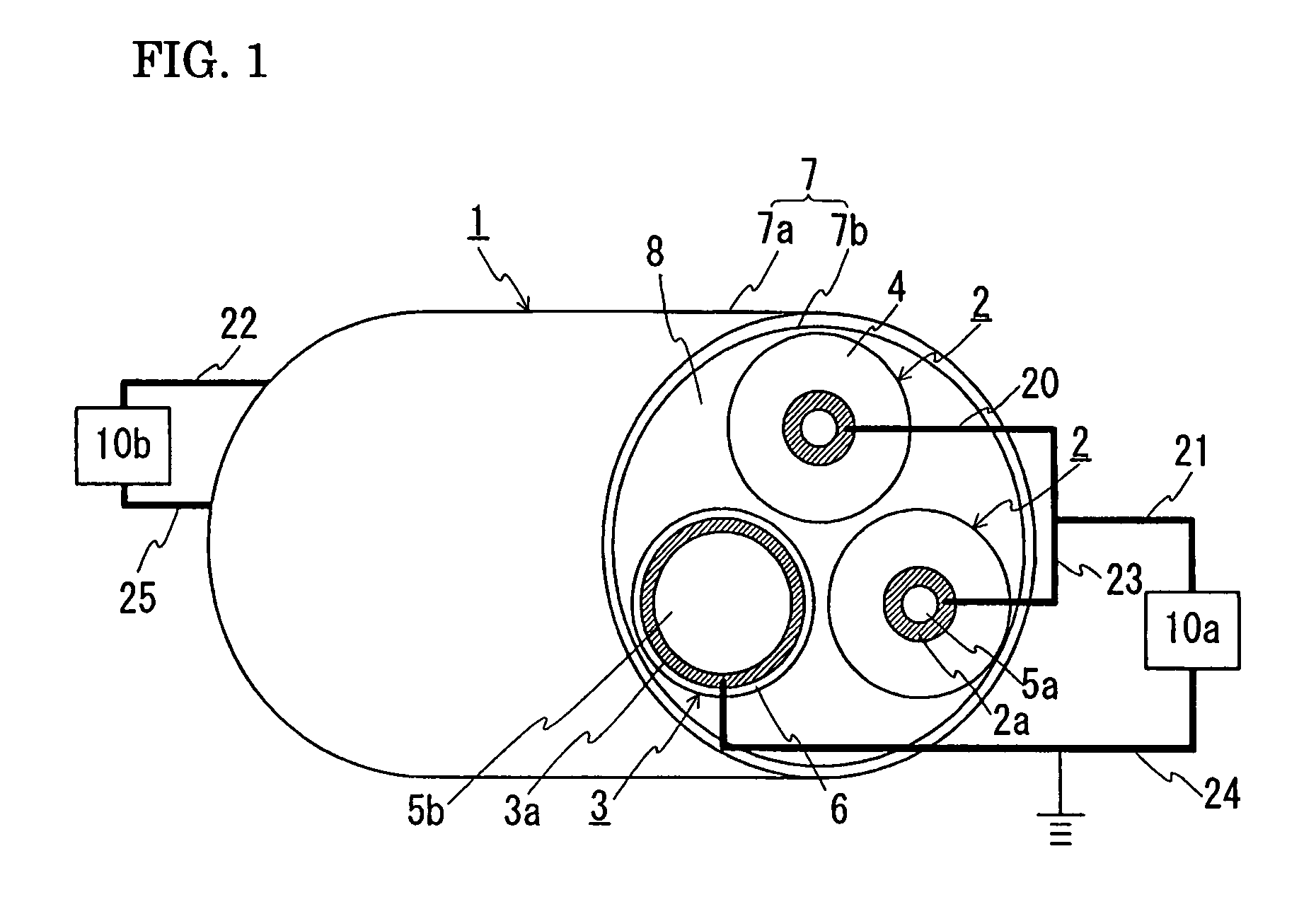
[0081]FIG. 1 is a schematic configuration diagram showing a state in which a DC transmission line for unipolar transmission is constructed by using a superconducting cable of the present invention. In the following drawing, the same sign indicates the same item. A superconducting cable 1 is formed by twisting together two types of cores (two first cores 2 and one second core 3) having different structures and then housing the twisted cores in a heat-insulated pipe 7. More specifically, the first cores 2 are each provided with a first superconducting layer 2a composed of a superconducting material at the inner-circumference side of an insulating layer 4 and is not provided with a layer composed of a superconducting material at the outer-circumference side of the insulating layer 4. The second core 3 is provided with a core member 5b at the center-portion side, is provided with a second superconducting layer 3a composed of a superconducting material at the outer-circumference side of ...

example 2

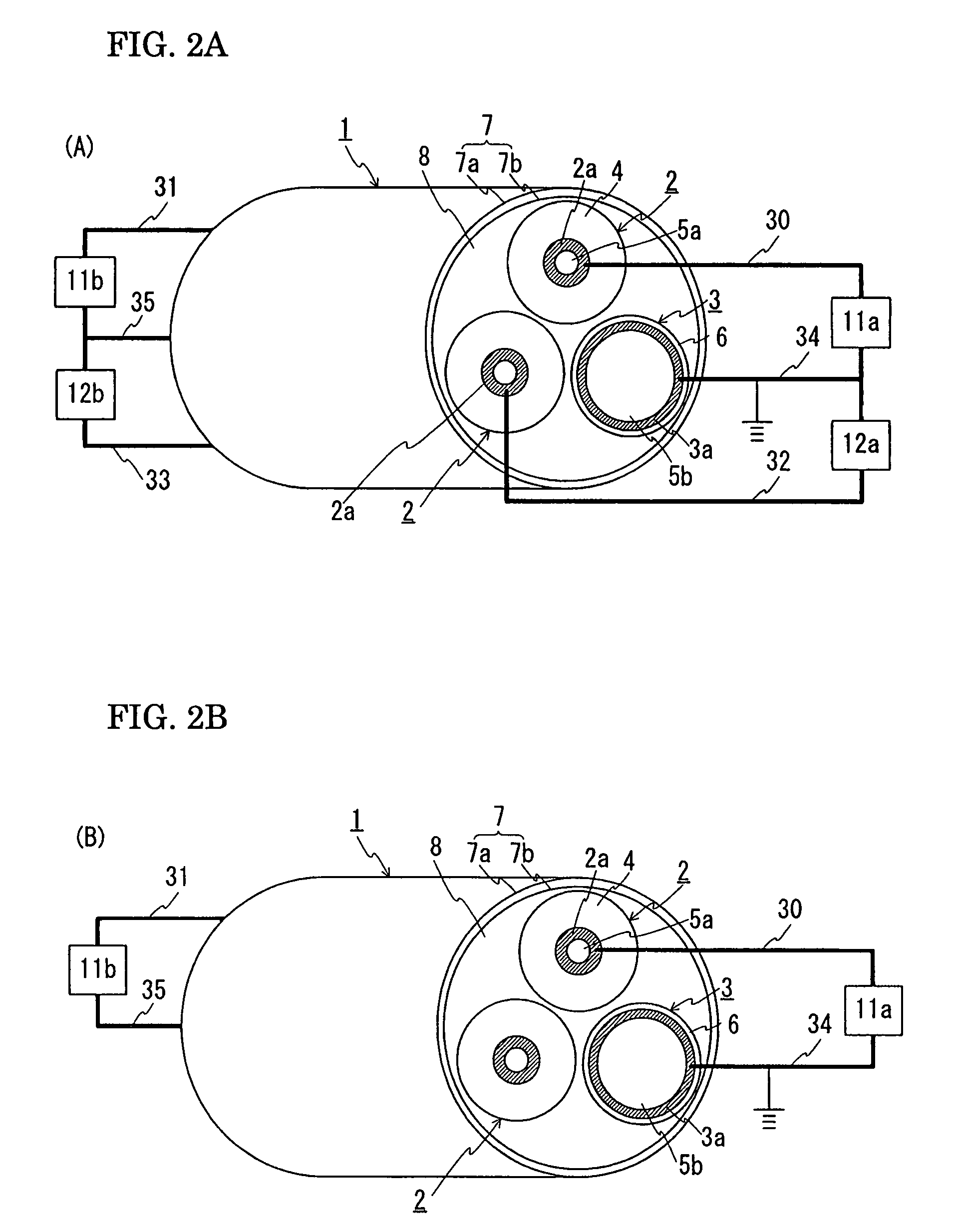
[0090]Next, the case where a bipolar transmission is performed is explained. FIG. 2(A) is a schematic configuration diagram showing a state in which a DC transmission line for bipolar transmission is constructed by using a superconducting cable of the present invention. FIG. 2(B) is a schematic configuration diagram showing a state in which a DC transmission line for unipolar transmission is constructed by using one first core of the two first cores and the second core. The superconducting cable 1 used in Example 1 can also be used for bipolar transmission. To perform the bipolar transmission, it is recommendable to construct a transmission line as shown in FIG. 2(A). More specifically, one end of the first superconducting layer 2a provided in one of the two first cores 2 (in FIG. 2(A), the first core 2 at the top) is connected to a DC-AC converter 11a, which is connected to an AC system (not shown), through a lead 30. The other end of the same first superconducting layer 2a is conn...

example 3

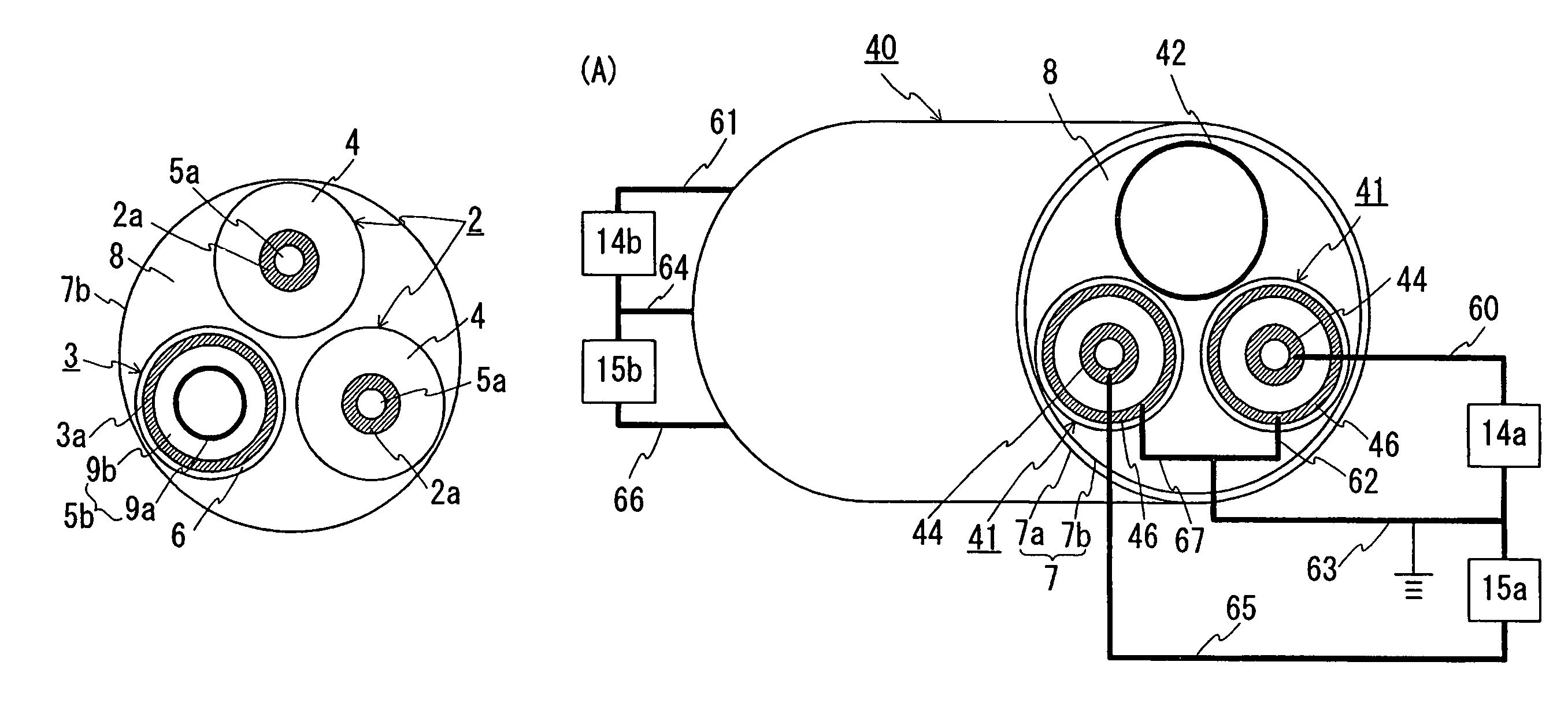
[0097]In the above-described Examples 1 and 2, an explanation is given to the structure in which a stranded copper wire is used as the core member of the second core. However, a coolant-circulating pipe may be used as the core member. FIG. 3 is a schematic cross-sectional view showing a superconducting cable of the present invention that is provided with a coolant-circulating pipe at the inside of the second superconducting layer of the second core. The second core 3 shown in this example has the same basic structure as that shown in Examples 1 and 2. Only the different point is that a coolant-circulating pipe 9a is provided as an inner core member of the core member 5b. An explanation is given below by focusing on this point.

[0098]In this example, the coolant-circulating pipe 9a was formed with a corrugated stainless steel pipe. An insulating layer 9b was formed on the outer circumference of the coolant-circulating pipe 9a by helically lapping semisynthetic insulating layer. In thi...


PUM

PropertyMeasurementUnit
diameteraaaaaaaaaa
thicknessaaaaaaaaaa
sizeaaaaaaaaaa

Abstract

The invention offers a superconducting cable easy to form a twisted structure even when a plurality of cable cores are used and a DC transmission system incorporating the superconducting cable. A superconducting cable 1 has a structure formed by twisting together two types of cable cores (two first cores 2 and one second core 3) having different structures and then housing them in a heat-insulated pipe 7. The first cores 2 each have a first superconducting layer 2a, to be used either as an outward line or for the transmission for a pole in DC transmission, and have no superconducting layer other than the first superconducting layer 2a. The second core 3 has a second superconducting layer 3a, to be used as a return line or neutral line in DC transmission, and has no superconducting layer other than the second superconducting layer 3a. The second superconducting layer 3a has an inner diameter larger than the outer diameter of the first superconducting layer 2a.

Description

TECHNICAL FIELD[0001]The present invention relates to a superconducting cable formed by twisting a plurality of cable cores together and to a DC transmission system incorporating the superconducting cable. The present invention particularly relates to a superconducting cable that allows easy formation of the twisted structure.BACKGROUND ART[0002]As an AC superconducting cable, a three-core-twisted-type cable is commonly known that is formed by twisting three cable cores together. FIG. 7 is a cross-sectional view of a three-core-twisted-type cable for the three-phase AC use. A superconducting cable 100 has a structure in which three cable cores 102 are twisted together and housed in a heat-insulated pipe 101. The heat-insulated pipe 101 has a dual-pipe structure composed of an outer pipe 101a and an inner pipe 101b, between which a heat-insulating material (not shown) is placed. The space between the outer pipe 101a and the inner pipe 101b is evacuated in vacuum. An anticorrosion cov...

Claims


Application Information

Patent Timeline
Patent Type & Authority Patents(United States)
IPC IPC(8): H01B12/00
CPCH01B12/06H01B12/16Y02E40/647Y02E40/642Y02E40/60H01B12/08
Inventor HIROSE, MASAYUKI
Owner SUMITOMO ELECTRIC IND LTD
Why Eureka
Try Eureka