A lamination equipment for lithium ion battery processing

A lithium-ion battery and stacking technology, which is applied in secondary batteries, battery assembly machines, secondary battery manufacturing, etc., can solve the problems of pole piece damage, lower stacking efficiency, and large horizontal space, and achieve high processing efficiency , Lamination effect is good, and the effect of convenient feeding

Inactive Publication Date: 2021-07-30
南京溧水高新产业股权投资有限公司
View PDF3 Cites 0 Cited by
  • Summary
  • Abstract
  • Description
  • Claims
  • Application Information

AI Technical Summary

Problems solved by technology

[0005] At present, the lamination of some lithium-ion power batteries is completed by manual lamination and mechanical winding method. Among them, the manual lamination method is that employees alternately stack the positive and negative electrodes in the fixture according to the established requirements for lamination. , because this method needs to touch the pole piece by hand many times during the production process, the pole piece is seriously damaged, and due to the high labor intensity of the employees, the phenomenon of stacking more pole pieces, less stacking, and overlapping occurs from time to time; through When laminating mechanically, Z-type lamination is often used. When laminating, the diaphragm is released by reciprocating the winding mechanism, so that the diaphragm is arranged in a Z shape. At the same time, the feeding mechanism of the positive and negative electrodes also reciprocates accordingly, so that The positive and negative electrodes are divided into two parts for loading, which affects the processing efficiency
And the reciprocating distance of the mechanism depends on the size of the battery. When the battery size is larger, the reciprocating distance is also greater. The moving time will also reduce the stacking efficiency and occupy a larger horizontal space.

Method used


Image

  • A lamination equipment for lithium ion battery processing
  • A lamination equipment for lithium ion battery processing
  • A lamination equipment for lithium ion battery processing

Examples


Embodiment 1

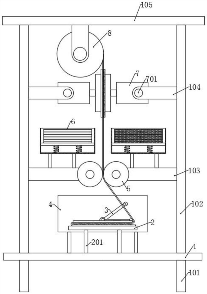
[0035] Please refer to the accompanying drawings, the present invention provides a technical solution: a lamination equipment for lithium ion battery processing, including a base plate 1, lower support rods 101 are fixed at the four corners of the bottom surface of the bottom plate 1, and upper support rods 101 are fixed at the four corners of the top surface. Support rod 102, the first support 103 is fixed between the bottom of the upper support rod 102, the second support 104 is fixed symmetrically on the upper part, and a top plate 105 is fixed together on the top, and a workbench 2 is arranged above the bottom plate 1, and the working The bottom surface of the platform 2 is correspondingly connected with the base plate 1 through the connecting rod 201. The two sides of the workbench 2 are symmetrically provided with the laminated assembly 3, and the outer side of the laminated assembly 3 is symmetrically provided with the driving box 4, and the driving box 4 is provided with...

Embodiment 2

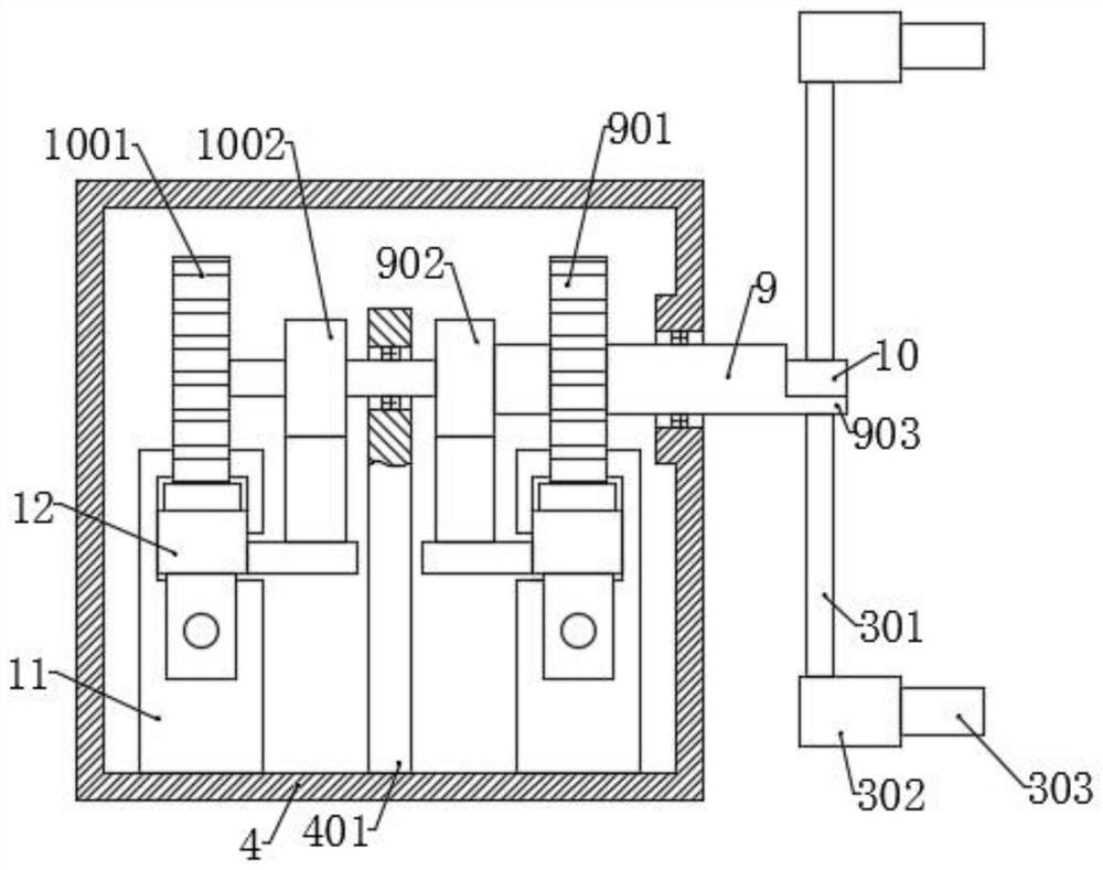
[0044] On the basis of Embodiment 1, an arc-shaped plate 903 is also fixed on the outer end of the rotating cylinder 9. The central angle corresponding to the arc-shaped plate 903 is 30°, and the inner and outer surfaces of the rotating cylinder 9 are in line with the inside and outside of the rotating cylinder 9. The sides are coincident, and the outer end coincides with the outer end of the rotating shaft 10. The fixing rods 301 of the two laminations 3 are respectively fixed on the outer side of the arc-shaped plate 903 and the rotating shaft 10, and the two fixing rods 301 are connected to the rotating shaft 10. The distances between the outer ends of the rotating shafts 10 are equal.

[0045] By setting the fixed rod 301 on the circular arc plate of the rotating cylinder 9, while not affecting the rotation of the rotating shaft 10, the lamination assemblies 3 on both sides are in the same plane, so that the structure of two lamination assemblies 3, The size and the like a...

Embodiment 3

[0047] On the basis of Embodiment 1, the bottom end of the connecting rod 201 passes through the bottom plate 1 and protrudes, and the extending end is fixed to the limit plate 202, and the connecting rod 201 is also sleeved with a first spring 203, and works The bottom surface of the platform 2 is correspondingly connected with the top surface of the bottom plate 1 through the first spring 203 .

[0048] When the battery stacks are accumulated to a certain thickness, there will be a gap between the height of the top surface and the original position. Therefore, the thickness of the battery will affect the work of the stack assembly 3. When the first spring 203 is used to rotate the pressing plate 303, the stack assembly 3 will pass The pressing effect of the pressing piece 303 and the first spring 203 enable the workbench 2 to move downward, eliminating the influence of the thickness of the battery.


PUM

PropertyMeasurementUnit
thicknessaaaaaaaaaa

Abstract

The invention discloses a lamination equipment for lithium-ion battery processing in the technical field of battery processing, including a workbench, a lamination assembly, a drive box, an adjustment wheel, a feeding mechanism, a storage mechanism and a coiling wheel. The material wheel is discharged intermittently. When the coil wheel is stopped, the feeding mechanism carries out the material loading and patching. When the coil wheel moves, the adjustment wheel moves synchronously. Type laminations, each mechanism cooperates to move; two storage boxes are respectively placed with positive and negative electrodes, when the vacuum suction cup absorbs the pole piece, the pressing motor rotates, driving the pressure wheel to separate from the pole piece, so as to control the movement of the vacuum suction cup After the vacuum suction cup leaves, the pressure roller returns to its original position to press the pole piece; by moving the rack, the corresponding rotating shaft and rotating cylinder can realize the process of stationary, forward rotating, stationary and reverse rotating, and the rotating shaft and rotating The movement time of the barrel is staggered. The Z-shaped laminations are thereby realized through the lamination assembly.

Description

technical field [0001] The invention relates to the technical field of battery processing, in particular to a lamination equipment for lithium ion battery processing. Background technique [0002] Lithium-ion battery is a secondary battery (rechargeable battery), which mainly relies on lithium ions to move between the positive and negative electrodes to work. During the charging and discharging process, Li+ intercalates and deintercalates back and forth between the two electrodes. When charging, Li+ is deintercalated from the positive electrode and embedded in the negative electrode through the electrolyte, and the negative electrode is in a lithium-rich state; the opposite is true during discharge. [0003] The main composition and structure of a lithium-ion battery includes a positive electrode, a separator, a negative electrode, an organic electrolyte, and a battery casing; among them, the active material of the positive electrode is generally lithium manganese oxide or l...

Claims


Application Information

Patent Timeline
Patent Type & Authority Patents(China)
IPC IPC(8): H01M10/04H01M10/0583
CPCH01M10/0404H01M10/0583Y02E60/10Y02P70/50
Inventor 尹娜
Owner 南京溧水高新产业股权投资有限公司
Why Eureka
Try Eureka