
Coupler

A coupler and main coupling technology, applied in the field of couplers, can solve the problems of increased cost, large size of couplers, and excessively long microstrip lines, and achieve the effects of cost saving, excellent intermodulation performance, and wiring space saving.

Pending Publication Date: 2020-04-17
DONGGUAN ACE TECH
View PDF0 Cites 1 Cited by
  • Summary
  • Abstract
  • Description
  • Claims
  • Application Information

AI Technical Summary

Problems solved by technology

Especially when it is applied in the low frequency band, due to the low frequency, the length of the required microstrip line is too long, which results in a larger size of the coupler and a corresponding increase in the cost

Method used


Image

  • Coupler
  • Coupler
  • Coupler

Examples


Embodiment Construction

[0018] In order to describe the technical content and structural features of the present invention in detail, further description will be given below in conjunction with the implementation and accompanying drawings.

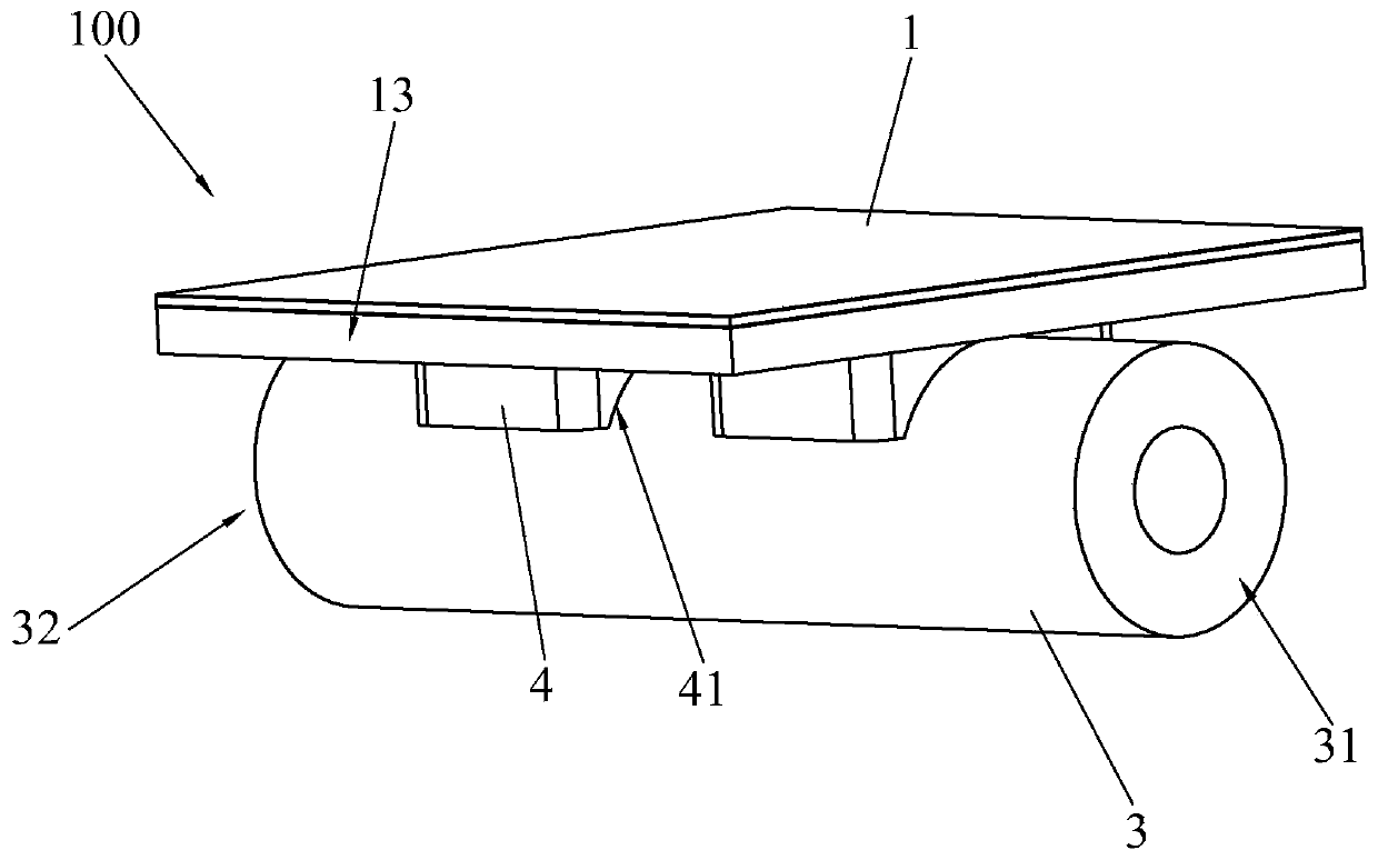
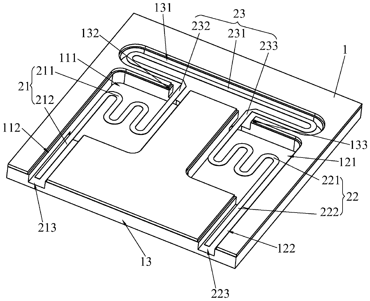
[0019] see figure 1 and figure 2 , the present invention provides a coupler 100, including a substrate 1, a microstrip line disposed on the substrate 1, and a coaxial cable 3 fixed on the substrate 1. The two ends of the coaxial cable 3 are signal input port 31 and signal input port 31 respectively. Output port 32, the radio frequency signal is input by signal input port 31, and is output by signal output port 32; The two connection lines 232, 233 at the two ends of the body 231, the two main coupling lines 21, 22 are respectively connected to the two connection lines 232, 233, and the free ends of the two main coupling lines 21, 22 are respectively the isolation port 213 and the coupling port 223, The main coupling lines 21 and 22 are bent structures. Wherei...


PUM


Abstract

The invention discloses a coupler. The coupler comprises a substrate, a microstrip line arranged on the substrate and a coaxial line fixed on the substrate, two ends of the coaxial line are respectively a signal input port and a signal output port; the microstrip line comprises two main coupling lines and an auxiliary coupling line, the auxiliary coupling line comprises a bent body and two connecting lines connected to the two ends of the body, the two main coupling lines are connected to the two connecting lines respectively, the free ends of the two main coupling lines are a coupling port and an isolation port respectively, and the main coupling line is of a bent structure. Through coupling of the coaxial line and the microstrip line, the signal loss is reduced, and the intermodulation performance is excellent; and moreover, the microstrip line comprises the two main coupling lines and the auxiliary coupling line, and the two main coupling lines and the auxiliary coupling line are bent, so that the wiring space required by the microstrip line is saved, the miniaturization design is realized, and the bandwidth of the coupler is increased.

Description

technical field [0001] The invention relates to the technical field of antenna design, in particular to a coupler with wide bandwidth and small volume. Background technique [0002] The coupler is a general-purpose microwave / millimeter wave component, which can be used for signal isolation, separation and mixing, such as power monitoring, source output power stabilization, signal source isolation, frequency sweep testing of transmission and reflection, etc. With the development of wireless communication systems, the requirements for communication devices are getting higher and higher. Not only the coupler is required to have a smaller port voltage standing wave ratio and a larger port isolation, but also the coupler is required to be small in size, The bandwidth is large. Especially when it is applied in the low frequency band, due to the low frequency, the length of the required microstrip line is too long, which results in a larger size of the coupler and a corresponding ...

Claims


Application Information

Patent Timeline
Patent Type & Authority Applications(China)
IPC IPC(8): H01P5/16
CPCH01P5/16
Inventor 金钟旭钟锡良
Owner DONGGUAN ACE TECH
Learn More