Wireless power transmission system

A wireless power transmission and power technology, applied in circuit devices, electrical components, etc., can solve the problems of slow loop control response and power failure, and achieve the effect of improving stability and reducing the number of power failures.

Active Publication Date: 2020-04-17
HUAWEI DIGITAL POWER TECH CO LTD
View PDF5 Cites 10 Cited by
  • Summary
  • Abstract
  • Description
  • Claims
  • Application Information

AI Technical Summary

Problems solved by technology

However, this wireless power transmission method requires a fast response from the transmitter, while the response of the loop control is sl

Method used


Image

  • Wireless power transmission system
  • Wireless power transmission system
  • Wireless power transmission system

Examples


Embodiment Construction

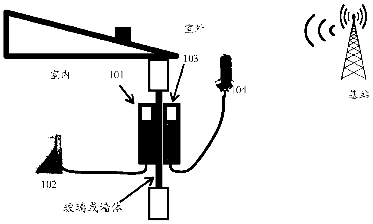
[0148] Such as figure 1As shown, the indoor unit may include a wireless power supply unit 101 and a load 102 (such as a wireless / laser modem), the outdoor unit may include a wireless power receiving unit 103 and a load 104 (such as a wireless / laser modem), and the indoor unit wirelessly supplies power to the outdoor unit. The indoor unit and the outdoor unit transmit electric energy between the wireless power supply unit 101 and the wireless power receiving unit 103 . In other implementation manners, the wireless power supply unit 101 is located in the outdoor unit, and the wireless power receiving unit is located in the indoor unit, that is, the outdoor unit provides electric energy for the indoor unit.

[0149] It should be noted that the wireless power transmission system provided by various embodiments of the present application is not only applicable to long-distance power transmission scenarios such as indoor units and outdoor units, but also applicable to wireless charg...


PUM


Abstract

The invention provides a wireless electric energy transmission system, which comprises a transmitting end and a receiving end, wherein the transmitting end comprises a DC/AC inverter circuit, a firstinductor and a first capacitor, the DC/AC inverter circuit, the first inductor and the first capacitor are connected in series, the receiving end comprises an AC/DC rectifying circuit, a second inductor and a second capacitor, the AC/DC rectifying circuit, the second inductor and the second capacitor are connected in series, the electric energy of the transmitting end is transmitted to the receiving end through electromagnetic induction between the first inductor and the second inductor, and the transmitting end is configured for: detecting the value of the resonant frequency of the transmitting end; detecting the value of the coupling coefficient between the transmitting end and the receiving end; calculating the value of the constant-voltage working frequency of the transmitting end according to the resonant frequency and the coupling coefficient; and controlling the working frequency of the DC/AC inverter circuit according to the calculated constant-voltage working frequency. The method can be specifically applied to a wireless charging or wireless power supply scene.

Description

technical field [0001] The present application relates to the field of circuits, in particular to a wireless power transmission system. Background technique [0002] Customer Premise Equipment (CPE) is a device that receives mobile signals and forwards them as wireless WIFI signals. Specifically, it is a device that converts 4G or 5G signals into WiFi signals. Such as figure 1 As shown, the CPE includes an outdoor unit (Outdoor Unit, ODU) and an indoor unit (Indoor Unit, IDU). During the transmission of signals from outdoors to indoors, because the signals need to penetrate walls or glass, the loss of mobile signals is large. Therefore, the mobile signal needs to be received by the outdoor unit ODU and transmitted to the indoor unit IDU, and the indoor unit IDU converts the mobile signal into a WiFi signal. In the existing CPE solution, the indoor unit and the outdoor unit are connected through a Power over Ethernet (POE) cable, and holes need to be drilled through the w...

Claims


Application Information

Patent Timeline
IPC IPC(8): H02J50/12H02J50/90
CPCH02J50/12H02J50/90H02J50/80
Inventor 吴宝善张成良吴东昊卢伟
Owner HUAWEI DIGITAL POWER TECH CO LTD
Why Eureka
Try Eureka