Reactor and method for continuous polymerisation

A technology for reactors and reactor shells, which is applied to tubular reactors. Reactors are used in the field of continuous production of polymers and synthetic rubbers. It can solve the problems of poor mixing and retention in reactors, undesired problems, etc.

Active Publication Date: 2020-04-17
ARLANXEO DEUT GMBH
View PDF10 Cites 2 Cited by
  • Summary
  • Abstract
  • Description
  • Claims
  • Application Information

AI Technical Summary

Problems solved by technology

By cooling only by the outer walls of the reactor, the cooling surface on an industrially relevant scale is small and the retention of poor mixing inside the reactor is large relative

Method used


Image

  • Reactor and method for continuous polymerisation
  • Reactor and method for continuous polymerisation
  • Reactor and method for continuous polymerisation

Examples


Embodiment

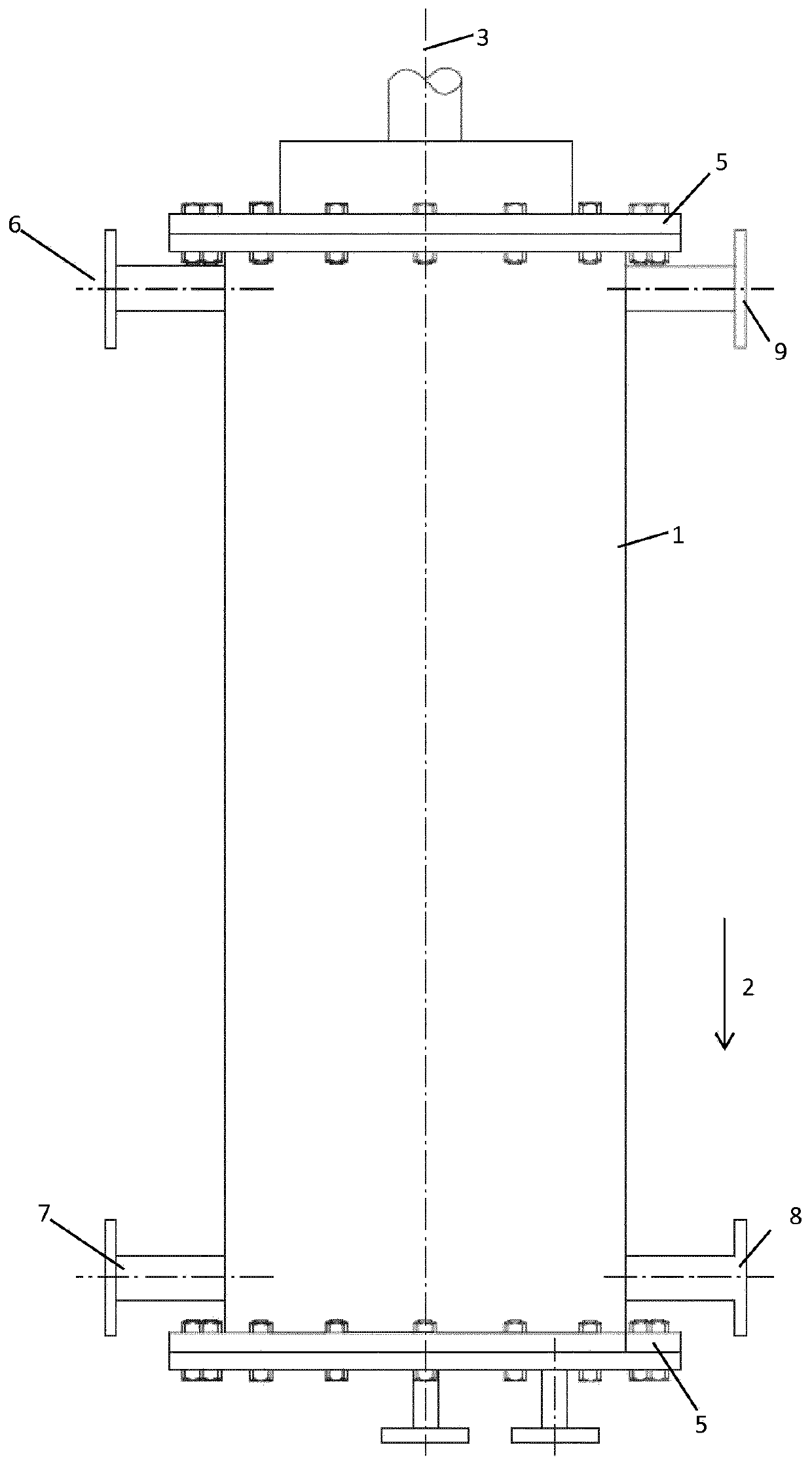
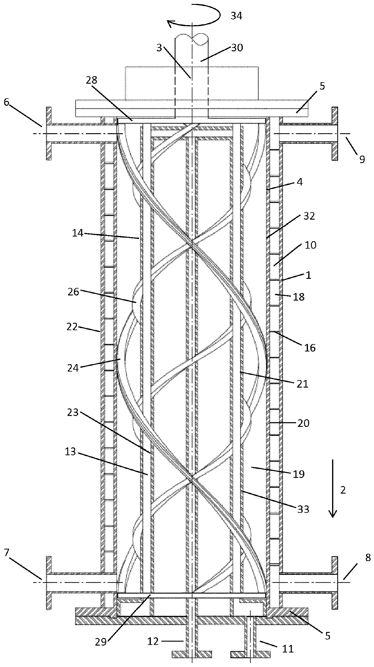
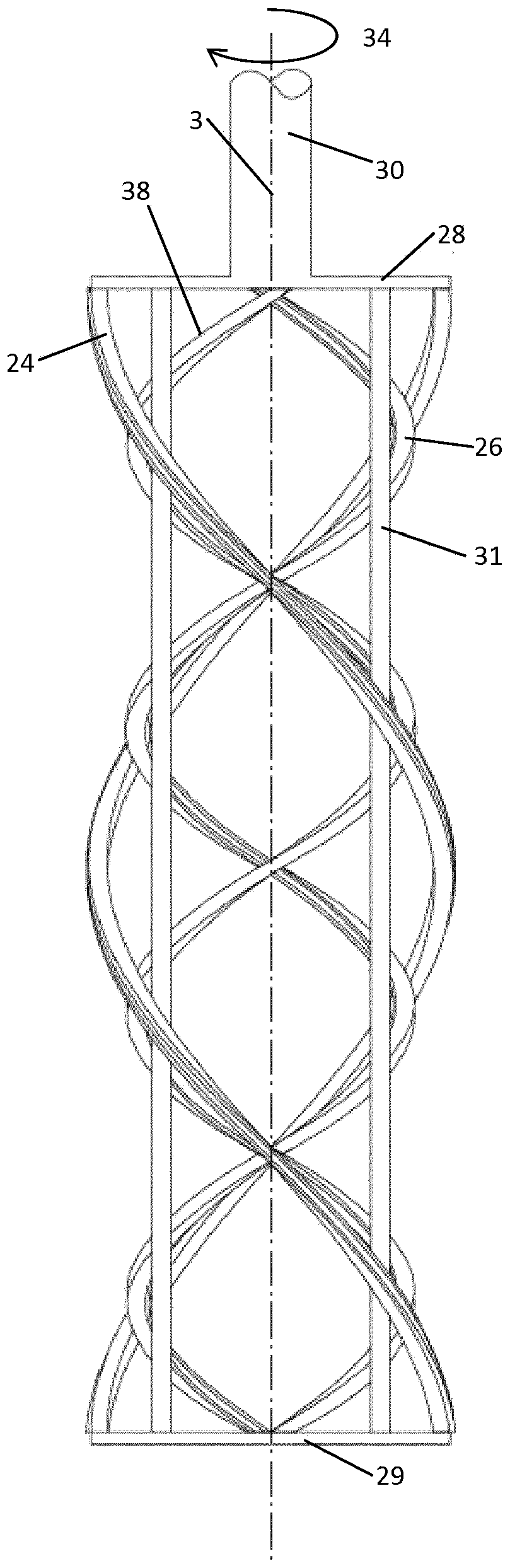
[0113] A reaction solution consisting of 33.5% by weight of solvent (alkane) and 1.5% by weight of isoprene and 65% by weight of isobutene as monomers was continuously metered into a test reactor with a length L of 320 mm and a diameter of D 100 mm (L / D=3.2), with a central displacement body with a displacement body diameter d of 70 mm (d / D=0.7) and a stirrer with four helical mixing elements throughout the reactor length, two of which A helical mixing element is in each case close to the wall on the outer surface of the reactor housing and two helical mixing elements are close to the wall on the surface of the inner displacement body (each at a distance of about 1 mm). The reactant flow was calibrated such that the average residence time in the reactor was 15 min. The reactor is completely filled with liquid.

[0114]To activate the polymerization, a solution of initiator (ethylaluminum dichloride, EADC) was additionally dosed in such an amount that the proportion of polymer...


PUM


Abstract

The invention relates to a reactor and to a method for continuous polymerisation, in which said reactor for the continuous production of polymers, particularly synthetic rubbers, contains at least onesubstantially tubular reactor housing (4), wherein said reactor housing (4) has a drive shaft (30) that is connected to at least one agitator (38) arranged such that it can rotate inside the reactorhousing (4), and the agitator contains at least one, and preferably two, three or four helical mixing elements (24) which are designed to be preferably close to the wall or to come into contact with the wall.

Description

technical field [0001] The present invention relates to a reactor, in particular a tubular reactor, to the use of such a reactor in a process for the continuous production of polymers, such as in particular synthetic rubber, and to the process itself. Background technique [0002] From US 4,282,925 a heat exchanger is known having a substantially tubular housing with a vertically extending central axis. The heat exchanger has scrapers extending along the inside of the housing by means of scraper blades. [0003] A disadvantage of this heat exchanger is that it does not allow axial mixing and thus in the case of strongly exothermic reactions heat is generated very locally at the inlet of the tubular reactor. This can lead to a sharp increase in temperature at this location, since the heat can only be removed insufficiently due to the small cooling area in the region of the reaction zone. In conclusion, such reaction conditions are difficult to control and it is almost impos...

Claims


Application Information

Patent Timeline
IPC IPC(8): B01J19/18B01J19/20
CPCB01J19/18B01J19/1812B01J19/20B01J2219/00085B01J2219/00094B01J2219/185B01J19/08
Inventor 罗尔夫·费尔勒汉斯-因戈尔夫·保罗保尔·瓦格纳乌多·维斯纳
Owner ARLANXEO DEUT GMBH
Why Eureka
Try Eureka