
Torque detector, and method for producing torque detector

A detector and substrate layer technology, which is applied in the direction of instruments, measuring devices, torque measurement, etc., can solve the problems of small gauge factor, difficult to detect strain, etc., and achieve the effect of improving detection accuracy

Active Publication Date: 2020-04-17
YAMATAKE HONEYWELL CO LTD
View PDF5 Cites 0 Cited by
  • Summary
  • Abstract
  • Description
  • Claims
  • Application Information

AI Technical Summary

Problems solved by technology

[0003] However, in metal strain gauges, the gauge factor (gauge factor) is small, so it is difficult to detect minute strains with high precision

Method used


Image

  • Torque detector, and method for producing torque detector
  • Torque detector, and method for producing torque detector
  • Torque detector, and method for producing torque detector

Examples


Embodiment approach 1

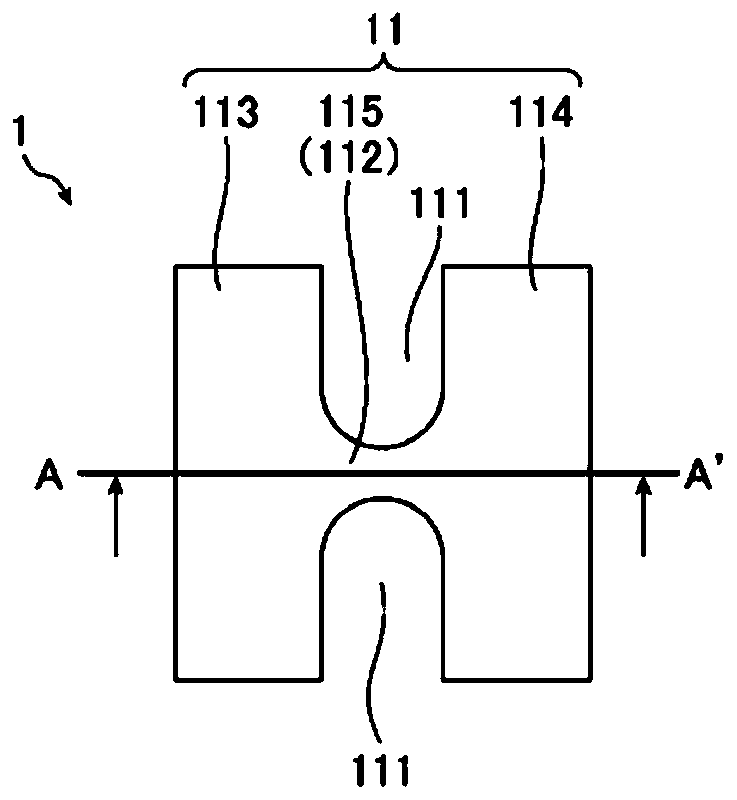
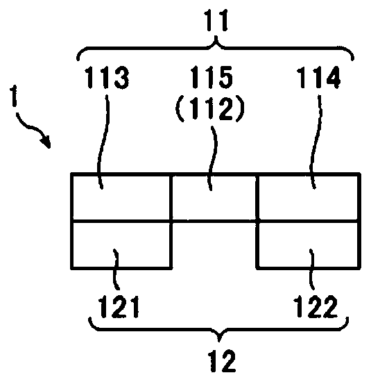
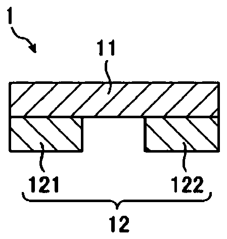
[0031] FIG. 1 is a diagram showing a configuration example of a torque detector according to Embodiment 1 of the present invention.

[0032] The torque detector detects the torque applied to the rotating shaft body 5 (see FIG. 4 ). One end of the rotating shaft body 5 in the axial direction is connected to a drive system 6 such as a motor, and the other end is connected to a load system such as a robot hand. As shown in FIG. 1 , the torque detector includes a strain sensor 1 .

[0033] The strain sensor 1 is a semiconductor strain gauge that is attached to the rotating shaft body 5 and outputs a voltage corresponding to shear stress (tensile stress and compressive stress) from the outside. The strain sensor 1 is implemented by a micro-electromechanical system (Micro ElectroMechanical Systems, MEMS). As shown in FIGS. 1 and 2 , the strain sensor 1 includes a silicon layer (substrate layer) 11 and an insulating layer 12 .

[0034] The silicon layer 11 is single crystal silico...


PUM


Abstract

The present invention is provided with: a silicon layer (11); a resistance gauge (13) which is formed in the silicon layer (11); slit portions (111) which are formed in the silicon layer (11), and which define a place where the resistance gauge (13) in the silicon layer (11) is formed as a local portion (112); and an insulation layer (12) which is joined to the silicon layer (11).

Description

technical field [0001] The present invention relates to a torque detector for detecting torque applied to a rotating shaft body and a manufacturing method of the torque detector. Background technique [0002] As one of the methods of detecting the torque applied to the rotating shaft body, there is a method in which a metal strain gauge (strain gauge) is installed on the peripheral surface of the rotating shaft body, and the resistance value of the metal strain gauge changes to detect the torque generated by the torque. The magnitude of the shear stress on the peripheral surface of the rotating shaft. In this form, four or more metal strain gauges are attached in a direction of 45 degrees with respect to the axial direction of the rotating shaft body to form a bridge circuit. [0003] However, in metal strain gauges, the gauge factor is small, so it is difficult to detect minute strains with high precision. [0004] On the other hand, as a method of improving the detection...

Claims


Application Information

Patent Timeline
Patent Type & Authority Applications(China)
IPC IPC(8): G01L3/10G01L3/14
CPCG01L3/10G01L3/14
Inventor 瀬戸祐希石仓义之小笠原里奈
Owner YAMATAKE HONEYWELL CO LTD
Learn More