
Crop transplanting machine

A technology for transplanting machines and crops, applied in the field of transplanting machines, can solve problems such as unprotected soil clods and root systems, affecting crop yield and quality, and brittle soil clods, so as to reduce mutual damage, reasonable design, The effect of protecting the root system

Inactive Publication Date: 2020-04-21
南安市三落工业设计有限公司
View PDF0 Cites 1 Cited by
  • Summary
  • Abstract
  • Description
  • Claims
  • Application Information

AI Technical Summary

Problems solved by technology

[0004] Aiming at the deficiencies in the prior art, the purpose of the present invention is to provide a crop transplanting machine to solve the problem that the soil clods and root systems of the crops are often not protected when transplanting in the prior art, and the soil clods are easy to be transplanted when transplanting. Fragmentation, causing the root system to be partially broken or even unable to survive after transplanting, which is likely to affect the yield and quality of crops

Method used


Image

  • Crop transplanting machine
  • Crop transplanting machine
  • Crop transplanting machine

Examples


Embodiment 1

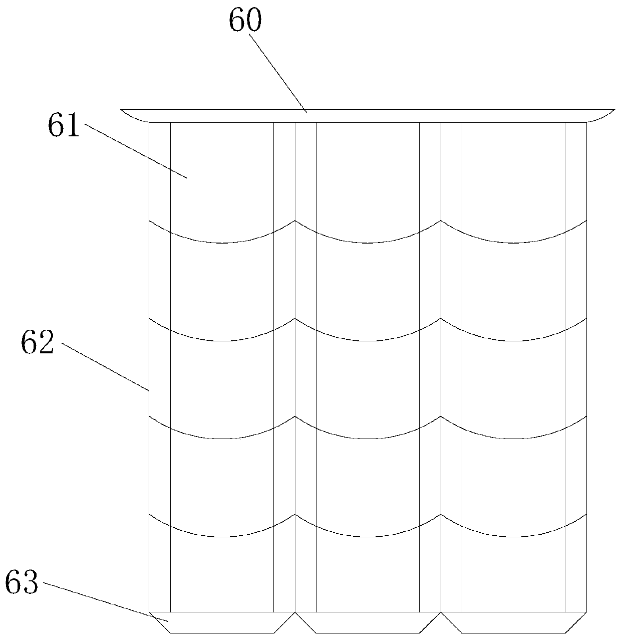
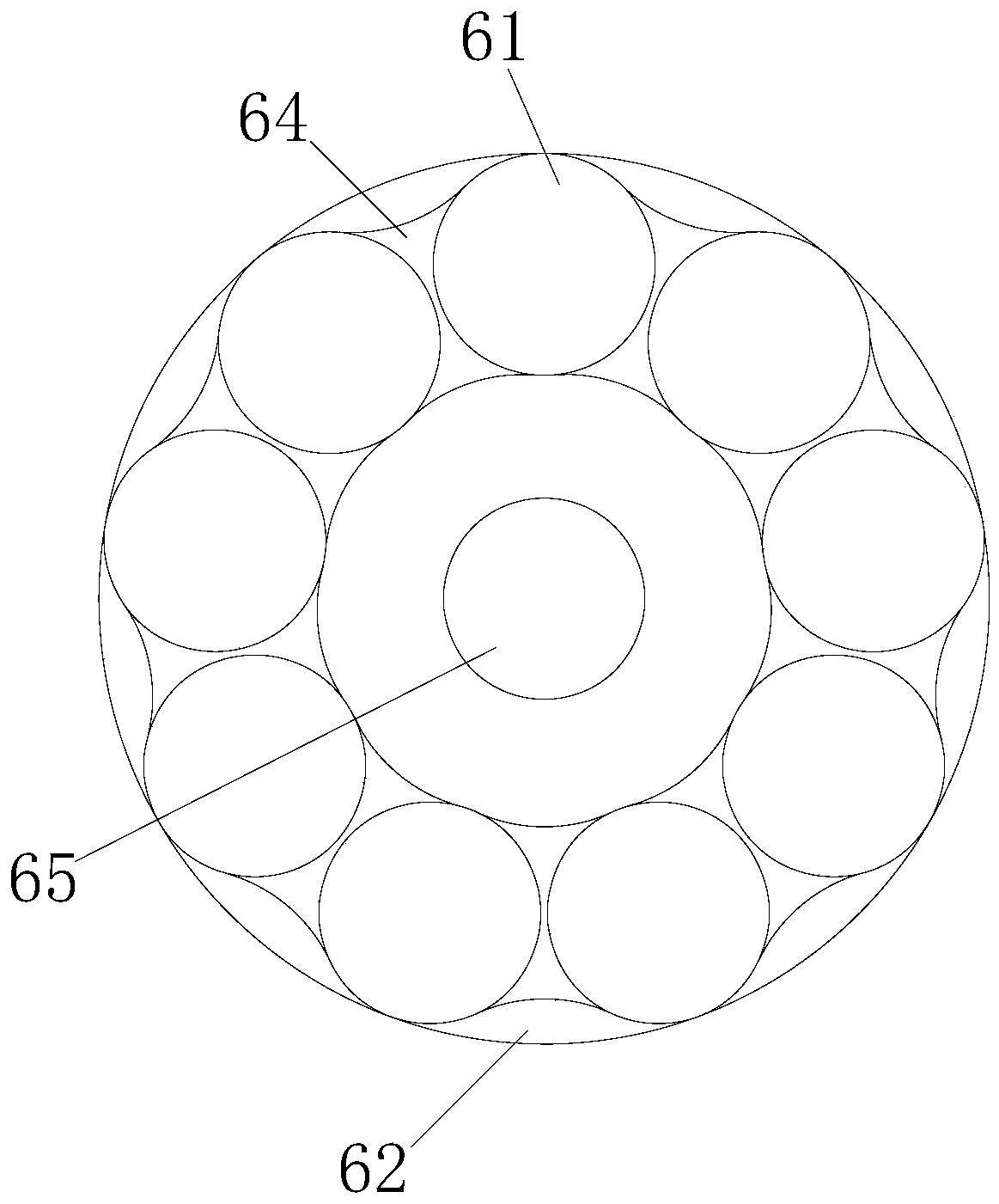
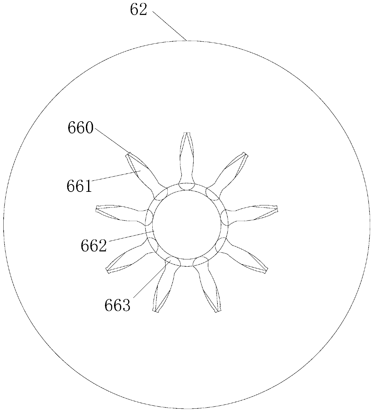
[0027] see Figure 1-Figure 6 , the present invention provides a kind of crop transplanting machine: its structure comprises the soil twisting drum 0, the front driving arm 1, the host supporting frame 2, the power starting wheel 3, the riding pile 4, the material storage box 5, the transplanting processing cylinder 6 The transplanting treatment cylinder 6 is vertically electric-welded on the top of the main machine support frame 2, and the two storage boxes 5 are respectively locked on the front and rear ends of the transplantation treatment cylinder 6 by rivets and communicate with each other. The front drive arm 1 is provided with two and is mechanically connected to the right side of the main frame 2, and the soil-opening winch 0 is located in the middle of the two front drive arms 1 and is movably connected with the main frame 2. The power starting wheel 3 is provided with two and is mechanically connected to the front and rear ends of the main frame 2, the riding pile 4 ...

Embodiment 2

[0030] On the basis of Example 1, please refer to Figure 7 , the moisturizing structure 64 is composed of a central column 640, a water-receiving bag 641, a moistening soil mouth 642, a clamp frame 643, and a water-guiding strip 644. At the left and right ends of the interior, the central column 640 is vertically threaded in the middle of the two water-receiving bladders, and more than two water guide strips 644 are provided and inserted into the upper and lower ends of the central column 640. The soil moistening port 642 is set at the upper and lower ends of the inner side of the clamp frame 643 and communicates with the water guide bar 644. When the transportation process is far away, the soil clods attached to the crops tend to lose moisture and are more likely to be broken under vibration. Root system, in order to ensure the normal transplanting of crops, let the water bag 641 be connected to the water tank in the equipment, flow into the water guide strip 644 through the...


PUM


Abstract

The invention discloses a crop transplanting machine. The structure of the transplanting machine includes a soil opening rotary wringing cylinder, front driving arms, a main machine supporting rack, power starting wheels, a riding pile, material storage boxes and a transplanting treatment cylinder; the transplanting treatment cylinder is vertically and electrically welded on the main machine supporting rack; and the two material storage boxes are respectively locked on the front and back ends of the transplanting treatment cylinder through rivets and communicate with each other. Crops are mutually separated through a reversing concave bag during transplanting, so that the crops cannot collide with each other, and mutual damage between the crops can be reduced; and through the elastic action of a two-fold arm and a center gasket, the local self-shaking of soil blocks can be achieved, so that the phenomenon of breaking cannot occur during transportation, and good protection on root integrity can be realized.

Description

technical field [0001] The invention relates to a transplanting machine, in particular to a crop transplanting machine. Background technique [0002] At present, biological cultivation is a relatively popular agricultural cultivation method. Due to the uncertainty of the environment, some seedlings often have a low survival rate in the natural environment. Planted crops have a root system, and the survival and integrity of the root system often affect the yield and quality of the crops when they mature. The current technical considerations are not comprehensive and have the following disadvantages: [0003] In the prior art, the soil clods and root systems of crops are often not protected when transplanted, and the soil clods are easily broken when transplanted, resulting in partial fracture of the root system or even failure to survive after transplanting, which easily affects the crops. output and quality. Contents of the invention [0004] Aiming at the deficiencies i...

Claims


Application Information

Patent Timeline
Patent Type & Authority Applications(China)
IPC IPC(8): A01C11/02
CPCA01C11/02
Inventor 乐志胜
Owner 南安市三落工业设计有限公司
Learn More