Precoated sand mold for casting

A coated sand and mold technology, applied in the direction of manufacturing tools, casting equipment, casting molding equipment, etc., can solve the problems of displacement deviation, damage, product deformation, etc., to reduce the attachment area, reduce the adhesion force, enhance the firmness effect

Active Publication Date: 2020-04-21
章丘市铜铝铸造厂
View PDF14 Cites 3 Cited by
  • Summary
  • Abstract
  • Description
  • Claims
  • Application Information

AI Technical Summary

Problems solved by technology

[0003] When using molds to produce steel castings and iron castings, in the process of casting products, the upper mold and the lower mold are generally used to close the mold to complete the shaping of the product. During the use of the

Method used


Image

  • Precoated sand mold for casting
  • Precoated sand mold for casting
  • Precoated sand mold for casting

Examples


Embodiment approach

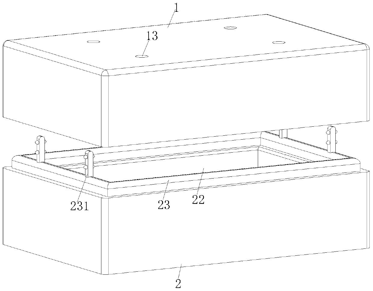
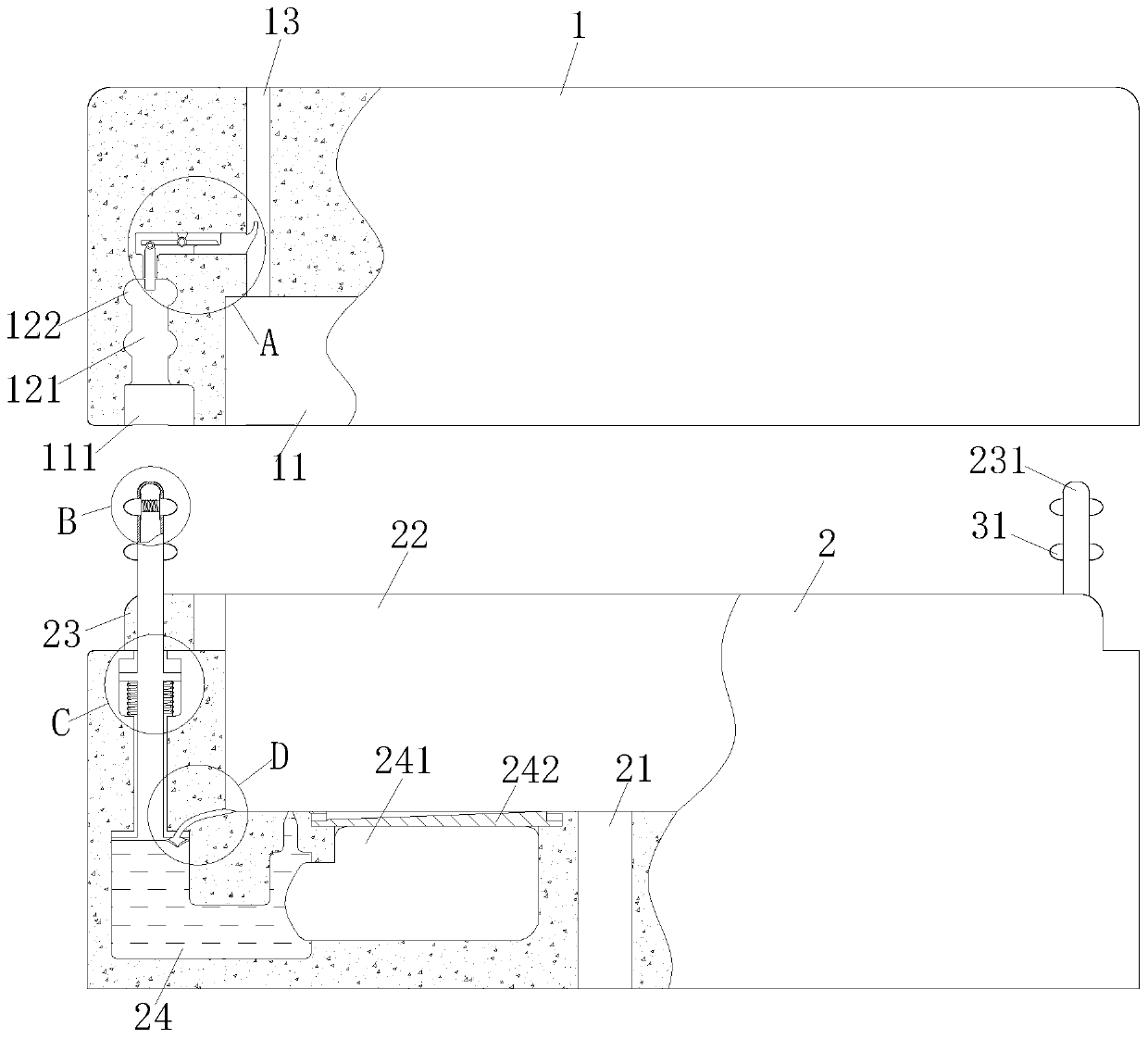
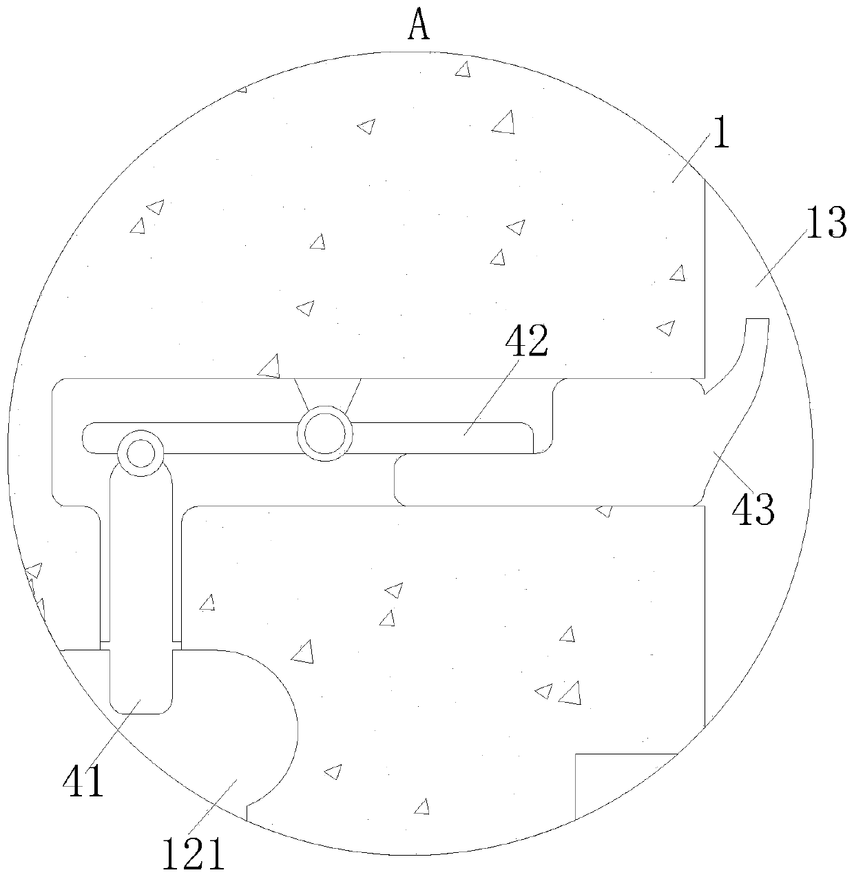
[0025] As a specific embodiment of the present invention, the positioning rod 231 is provided with a fastening unit 3; the fastening unit 3 includes a protrusion 31 and a No. 2 spring 32; Cavity 233, the protrusions 31 are symmetrically arranged in the first cavity 233, and the relative protrusions 31 are connected by the second spring 32; the side wall of the positioning hole 121 is provided with a semicircular card slot 122; through the fastening unit 3 and the card slot 122, to achieve a stable connection between the movable mold 1 and the fixed mold 2; when working, when the positioning rod 231 is stretched into the positioning hole 121, the protrusion 31 on the positioning rod 231 first extends into the positioning hole 121. In the slot 111, it is squeezed by the side wall of the positioning hole 121, and the protrusion 31 is squeezed into the first cavity 233. When the positioning rod 231 is fully inserted into the positioning hole 121, the protrusion 31 on the positionin...


PUM


Abstract

The invention belongs to the technical field of precoated sand molds and particularly relates to a precoated sand mold for casting. The mold comprises a movable mold and a fixed mold, a first mold cavity and a positioning groove are formed in the lower end face of the movable mold, and air outlet holes are symmetrically formed in the movable mold and communicate with the first mold cavity; a positioning groove is formed in the outer side of a cavity opening of the first mold cavity, positioning holes is formed in the positioning groove, and a fixed mold is arranged below the movable mold; a feeding channel is formed in the middle of a bottom end face of the fixed mold, the feeding channel communicates with a second mold cavity, and an upper end face of the fixed mold is provided with the second mold cavity and a strip-shaped block used for positioning. The accurate positioning and mold assembly between the movable mold and the fixed mold are achieved through the cooperation between positioning rods and the positioning holes, and anti-sticking silicone oil in tanhe oil storage cavity flows into the second mold cavity through the cooperation between the positioning rods and the oil storage cavity.

Description

technical field [0001] The invention belongs to the technical field of coated sand molds, in particular to a coated sand mold for casting. Background technique [0002] Coated sand, the surface of the sand particles is covered with a layer of solid resin film before molding or core sand. There are two coating processes: cold method and hot method: the cold method dissolves the resin with ethanol, and adds urotropine during the sand mixing process, so that the two are coated on the surface of the sand, and the ethanol volatilizes to obtain coated sand; Preheat the sand to a certain temperature, add resin to melt, stir to coat the resin on the surface of the sand, add urotropine aqueous solution and lubricant, cool, crush, and sieve to obtain coated sand. For steel castings and iron castings. [0003] When using molds to produce steel castings and iron castings, in the process of casting products, the upper mold and the lower mold are generally used to close the mold to comp...

Claims


Application Information

Patent Timeline
IPC IPC(8): B22C9/02B22C21/10B22C21/08B22D33/04
CPCB22C9/02B22C21/08B22C21/10B22D33/04
Inventor 张永苏桥娄王英
Owner 章丘市铜铝铸造厂
Why Eureka
Try Eureka