Sealing equipment of liquid filling machine

A technology of sealing equipment and filling machine, which is applied in liquid processing, packaging, closures, etc., can solve problems such as complex structures, and achieve the effect of flexible contact and avoiding impact

Pending Publication Date: 2020-04-21
协建(江苏)智能装备有限公司
View PDF6 Cites 1 Cited by
  • Summary
  • Abstract
  • Description
  • Claims
  • Application Information

AI Technical Summary

Problems solved by technology

[0003] The structure of the existing packaging device of the filling machine is relatively complicated, and the film needs to be cut during the packaging process so that the size of the film matches the bottle mouth

Method used


Image

  • Sealing equipment of liquid filling machine
  • Sealing equipment of liquid filling machine
  • Sealing equipment of liquid filling machine

Examples


Embodiment 1

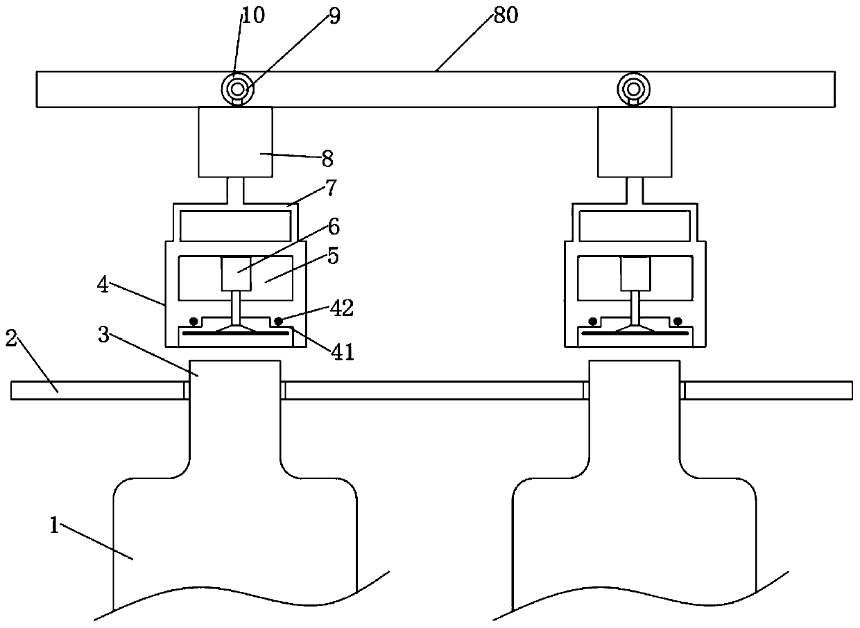
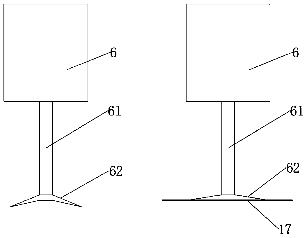
[0026] like Figure 1-4 As shown, a sealing device for a liquid filling machine includes a packaging frame 2, and plastic bottles 1 are uniformly placed in the packaging frame 2, and the bottle mouth 3 of the plastic bottle 1 is inserted into the packaging frame 2, and the bottle The upper side of the port 3 is provided with an encapsulation shell 4, the encapsulation shell 4 is fixedly connected with the mounting frame 7, the mounting frame 7 is connected with the pneumatic telescopic column 8, and the pneumatic telescopic column 8 is movably connected with the top plate 80. The pneumatic telescopic column 8 moves back and forth on the top plate 80, and the middle part of the packaging shell 4 is provided with a motor box 5, and the first motor 6 is arranged inside the motor box 5, and the first motor 6 and the telescopic rod 61 Connected, the end of the telescopic rod 61 is connected with a suction cup 62, the packaging shell 4 on the outer ring of the suction cup 62 is prov...

Embodiment 2

[0039] This embodiment is based on the embodiment 1 to specifically describe the working principle of a liquid filling machine sealing device shown in the embodiment 1.

[0040] A liquid filling machine sealing equipment, such as Figure 1-4 As shown, assemble.

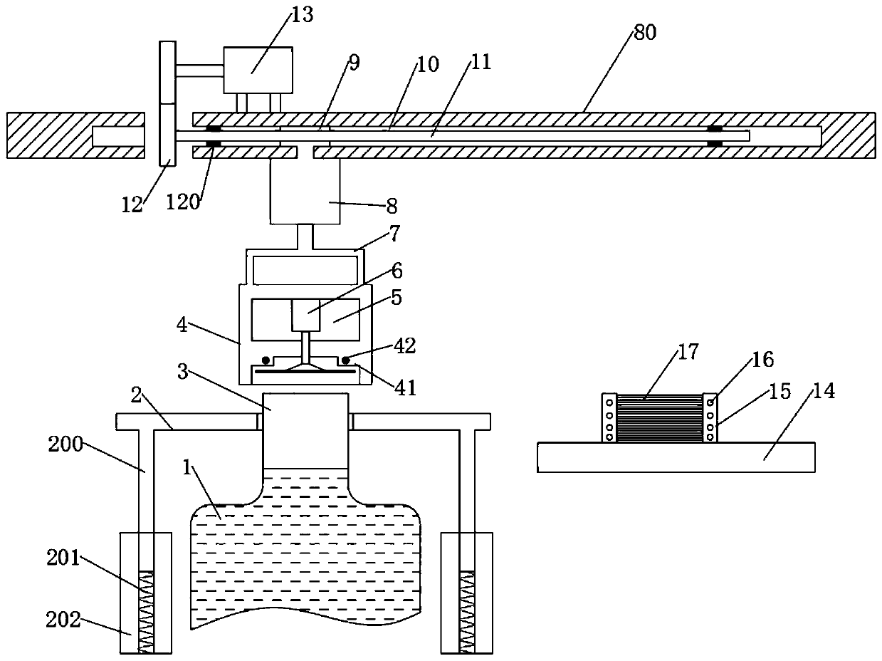
[0041] After the equipment is assembled, start the second motor 13, so that the pneumatic telescopic column 8 moves to the right in combination with the sleeve 9. When the sleeve 9 runs to the end of the right stroke, the second motor 13 is suspended, and the first motor 6 is started, so that the telescopic rod The sucker 62 on the 61 moves downward to suck the film body 17 in the film tube 15. After sucking, the first motor 6 drives the sucker 62 back to the initial height.

[0042]Then the second motor 13 drives the screw rod 11 to make the pneumatic telescopic column 8 move to the left. When the packaging shell 4 returns to the top of the bottle mouth 3, the pneumatic telescopic column 8 moves down, and the mounti...


PUM


Abstract

The invention discloses sealing equipment of a liquid filling machine, relates to the technical field of packaging equipment, and mainly solves a problem that the packaging equipment is complex in structure. The equipment includes a packaging frame, wherein plastic bottles are evenly placed in the packaging frame, bottle openings of the plastic bottles are inserted into the packaging frame, a packaging shell is arranged on an upper side of the bottle opening, the packaging shell is fixedly connected with a mounting frame, the mounting frame is connected with a pneumatic telescopic column, an upper side of the pneumatic telescopic column is connected with a sleeve, the sleeve is mounted in a mounting groove of a top plate, a motor box is arranged in the middle of the packaging shell, a first motor is arranged in the motor box, the first motor is connected with a telescopic rod, a tail end of the telescopic rod is connected with a suction cup, a containing table is arranged on the rightside of the packaging frame, a film cylinder is arranged on the containing table, and a film body is placed in the film cylinder. The equipment is advantaged in that the procedure of bottle opening film covering and packaging is simplified, and sealing efficiency is improved.

Description

technical field [0001] The invention relates to the technical field of packaging equipment, in particular to a sealing equipment for a liquid filling machine. Background technique [0002] Filled products usually need to be coated and packaged at the mouth of the bottle after filling. It is often used in the production and packaging of beverages, soybean milk, liquid medicines and other products. The coating is usually aluminum film, and hot melt adhesive is coated on one side of the film. The purpose of packaging is achieved by bonding hot melt adhesive to the bottle mouth. [0003] The structure of the existing packaging device of the filling machine is relatively complicated, and the film needs to be cut during the packaging process so that the size of the film matches the bottle mouth. Contents of the invention [0004] The purpose of the embodiments of the present invention is to provide a sealing device for a liquid filling machine to solve the problems raised in th...

Claims


Application Information

Patent Timeline
IPC IPC(8): B67B5/03
CPCB67B5/03
Inventor 廖明俞杰
Owner 协建(江苏)智能装备有限公司
Why Eureka
Try Eureka