Roof deformation joint structure and construction method thereof

A construction method and deformation joint technology, applied in the direction of roof, roof covering, roof using flat/curved panels, etc., can solve condensation, not fully considering the influence of roof panel deformation, polyethylene round rods are easily crushed, etc. question

Active Publication Date: 2020-04-21
JIANGSU PROVINCIAL CONSTR GRP CO LTD
View PDF10 Cites 3 Cited by
  • Summary
  • Abstract
  • Description
  • Claims
  • Application Information

AI Technical Summary

Problems solved by technology

[0004] The current method of deformation joint construction does not fully consider the influence of the deformation of the roof panel under the action of temperature stress, wind load and earthquake action on it
The current method is to stuff polyethylene rods in the deformation joints. After the cycle of alternating cold and hot weather, each component material in the construction method will undergo expansion and contraction deformation. Due to the different expansion coefficients, the deformation is inconsistent. The polyethylene rods filled in the deformation joints It is easy to be squeezed, and then there will be a gap at the deformation joint, causing the air in the deformation joint to communicate with the outside air, and accelerate the heat convection of the air
At the same time, rainwater is easy to leak into the roof through the gaps generated, resulting in thermal bridge phenomena such as mildew and condensation, which reduces the durability and efficacy of the insulation system

Method used


Image

  • Roof deformation joint structure and construction method thereof
  • Roof deformation joint structure and construction method thereof
  • Roof deformation joint structure and construction method thereof

Examples


Embodiment Construction

[0041] The present invention will be described in further detail below in conjunction with the accompanying drawings.

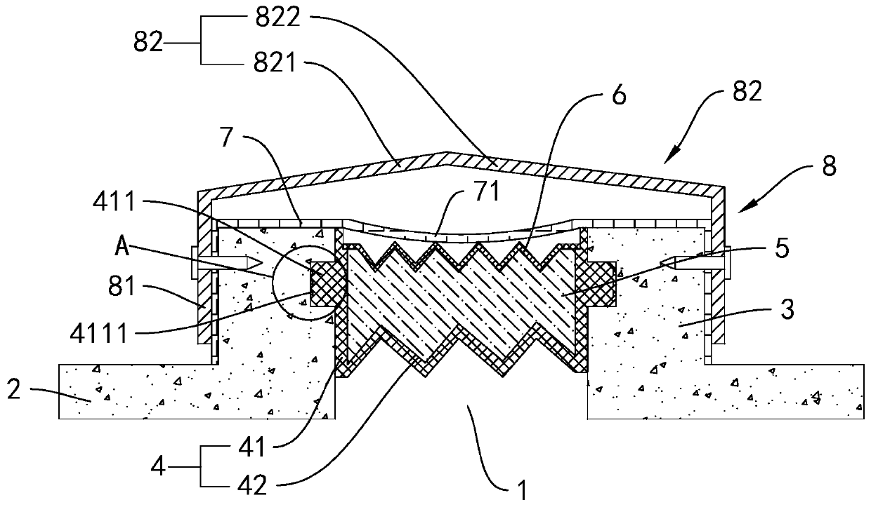
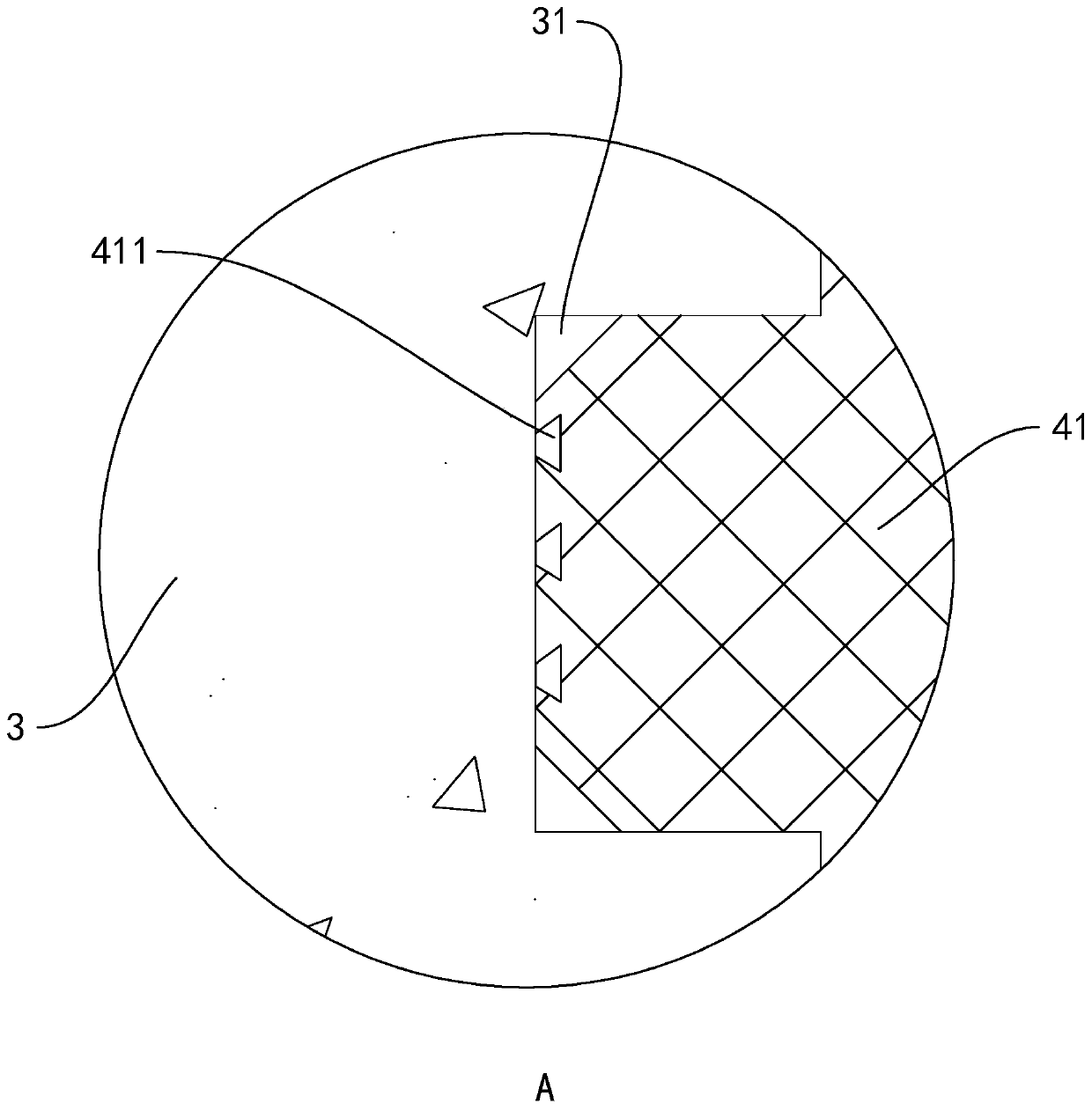
[0042] refer to figure 1 , is a roof deformation joint structure disclosed by the present invention, comprising a roof panel 2 with a deformation joint 1, and the top surface of the roof panel 2 is provided with bases 3 respectively located on both sides of the deformation joint 1, and the base 3 and the roof Panel 2 is integrally formed.

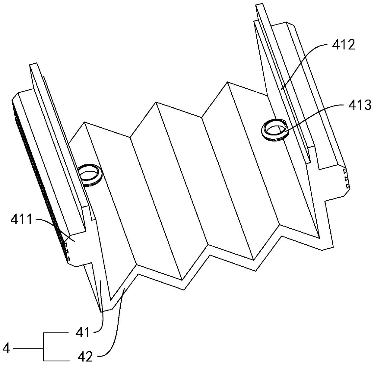
[0043] An elastic blocking member 4 is arranged between the two bases 3, and the blocking member 4 includes connecting plates 41 respectively attached to the opposite side surfaces of the two bases 3 and elastic parts between the connecting plates 41. The expansion and contraction part 42 is arranged along the width direction of the deformation seam 1 in the expansion and contraction direction of the elastic expansion and contraction part 42 . The elastic telescopic part 42 is integrally formed with the two connecting pl...


PUM


Abstract

The invention relates to a roof deformation joint structure. The roof deformation joint structure comprises a roof panel with a deformation joint. The upper surface of the roof panel is provided withbases located on the two sides of the deformation joint correspondingly. An elastic blocking member is arranged between the opposite bases. The blocking member comprises connecting plates attached tothe opposite side surfaces of the two bases correspondingly, and an elastic telescopic portion located between the two connecting plates. The telescoping direction of the elastic telescopic portion isthe same as the width direction of the deformation joint, and the elastic telescopic portion is in a pre-compressed state. An accommodating cavity with the top end being open is enclosed between theelastic telescopic portion and the two connecting plates. The accommodating cavity is filled with a flexible thermal insulation material. A top opening of the accommodating cavity is provided with a telescopic plate for closing the top opening of the accommodating cavity. The telescoping direction of the telescopic plate is the same as the telescoping direction of the elastic telescopic portion. Acover plate covering the two bases and the deformation joint is arranged above the bases. The roof deformation joint structure has the effect of ensuring the heat insulation performance at the roof deformation joint.

Description

technical field [0001] The invention relates to the technical field of building construction, in particular to a roof deformation joint structure and a construction method thereof. Background technique [0002] When the building is too long, in order to prevent deformation cracks caused by temperature changes, deformation joints should be provided. The leakage of deformation joints has been one of the most prominent quality problems in building construction for many years. It seriously affects the use function of the building and the overall quality of the project. A reasonable deformation joint waterproof structure is of great significance to prolong the service life of roof waterproofing projects. [0003] The Chinese patent with the authorized announcement number CN202850386U discloses a waterproof structure for light steel roof deformation joints, including steel purlins, light steel roof panels, galvanized iron sheets, linoleum, polystyrene insulation boards, hemp silk...

Claims


Application Information

Patent Timeline
Patent Type & Authority Applications(China)
IPC IPC(8): E04D3/38E04D13/15
CPCE04D3/38E04D13/151
Inventor 张春春鲁昌伍蒋科峰刘建东李赵荣
Owner JIANGSU PROVINCIAL CONSTR GRP CO LTD
Why Eureka
Try Eureka