Small double-stage hammer-shaped pin roller oscillating tooth speed reducer

A movable tooth reducer and hammer-shaped technology, which is applied to belts/chains/gears, transmission parts, mechanical equipment, etc., can solve the problems of difficult to achieve large reduction ratio transmission, large axial structure, etc., to improve rigidity, Improve the bearing capacity, the effect of large bearing capacity

Active Publication Date: 2020-04-21
YANSHAN UNIV
View PDF19 Cites 2 Cited by
  • Summary
  • Abstract
  • Description
  • Claims
  • Application Information

AI Technical Summary

Problems solved by technology

For example, the patent No. CN201910292297.6 proposes "A Double Shock Roller Movable Tooth Reducer with Backlash Elimination Mechanism". The two eccentric circular shocks are symmetrically arranged to eliminate inertial loads. Spring devices and tapered rollers are used. Movable teeth can eliminate axial clearance, but only one-stage reduction, it is difficult to achieve large reduction ratio transmission, and the axial structure is too large, not suitable for fields with limited space size

Method used


Image

  • Small double-stage hammer-shaped pin roller oscillating tooth speed reducer
  • Small double-stage hammer-shaped pin roller oscillating tooth speed reducer
  • Small double-stage hammer-shaped pin roller oscillating tooth speed reducer

Examples


Embodiment 1

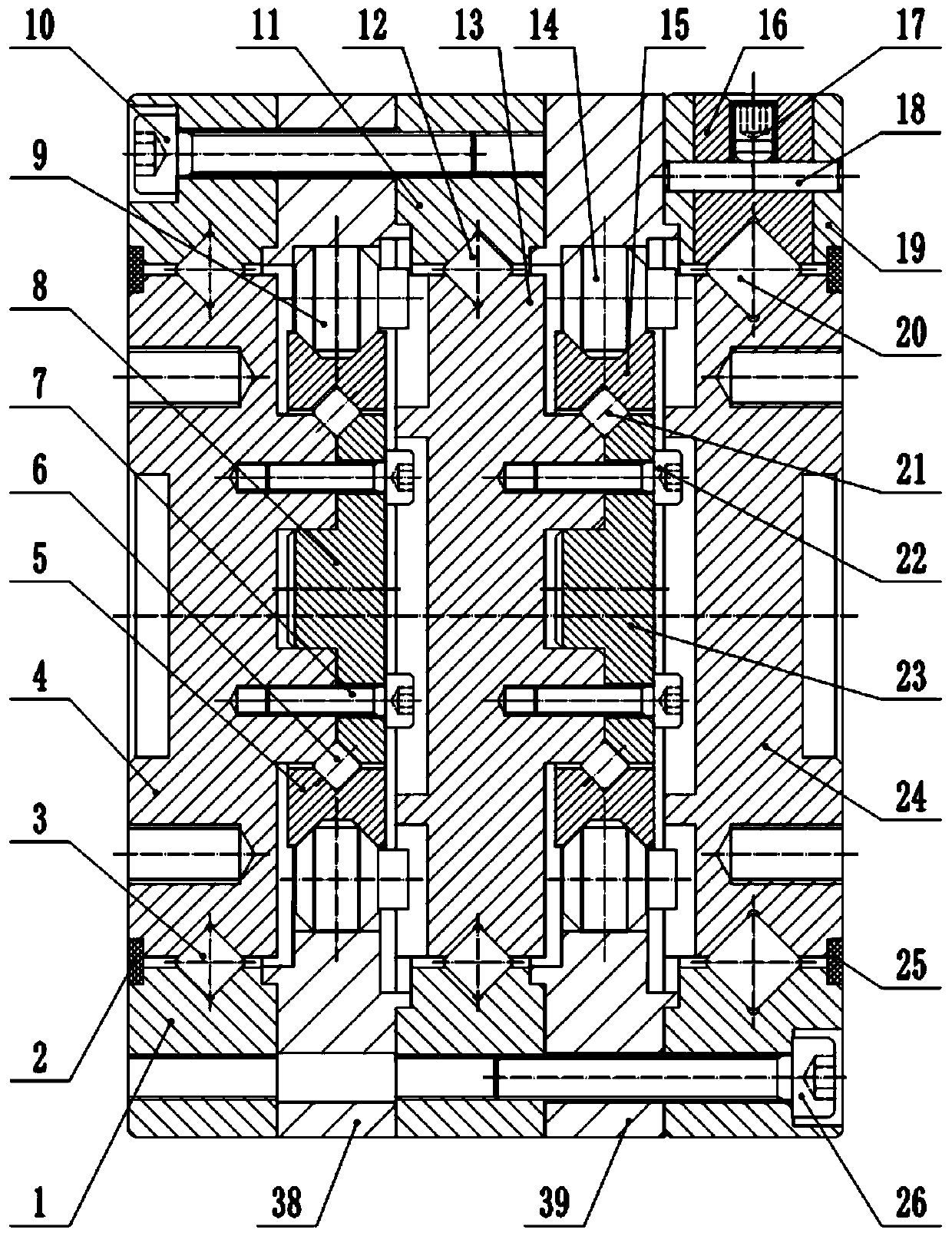
[0055] Such as figure 1 As shown, a small two-stage hammer roller movable tooth reducer is designed for a certain application occasion. As the preferred embodiment 1 of the present invention, its overall size is φ70mm in outer diameter and 48mm in length; the primary and secondary transmission The theoretical parameters are listed in Table 1.

[0056] Table 1 Example 1 Structural Theoretical Parameter Table

[0057]

[0058] Among them, the cone half-angles of the first cone surface 901 and the second cone surface 903 of the first-stage hammer roller movable tooth 9 and the second-stage hammer roller movable tooth 14 are both 45°, and the angle can be selected according to the actual stress situation. Certainly.

[0059] Such as Figure 1-8 As shown, a small double-stage hammer roller movable gear reducer includes a housing, in which an input shaft 4, a first-stage shock wave outer ring 5 hinged to each other and a first-stage shock wave are arranged in sequence along th...

Embodiment 2

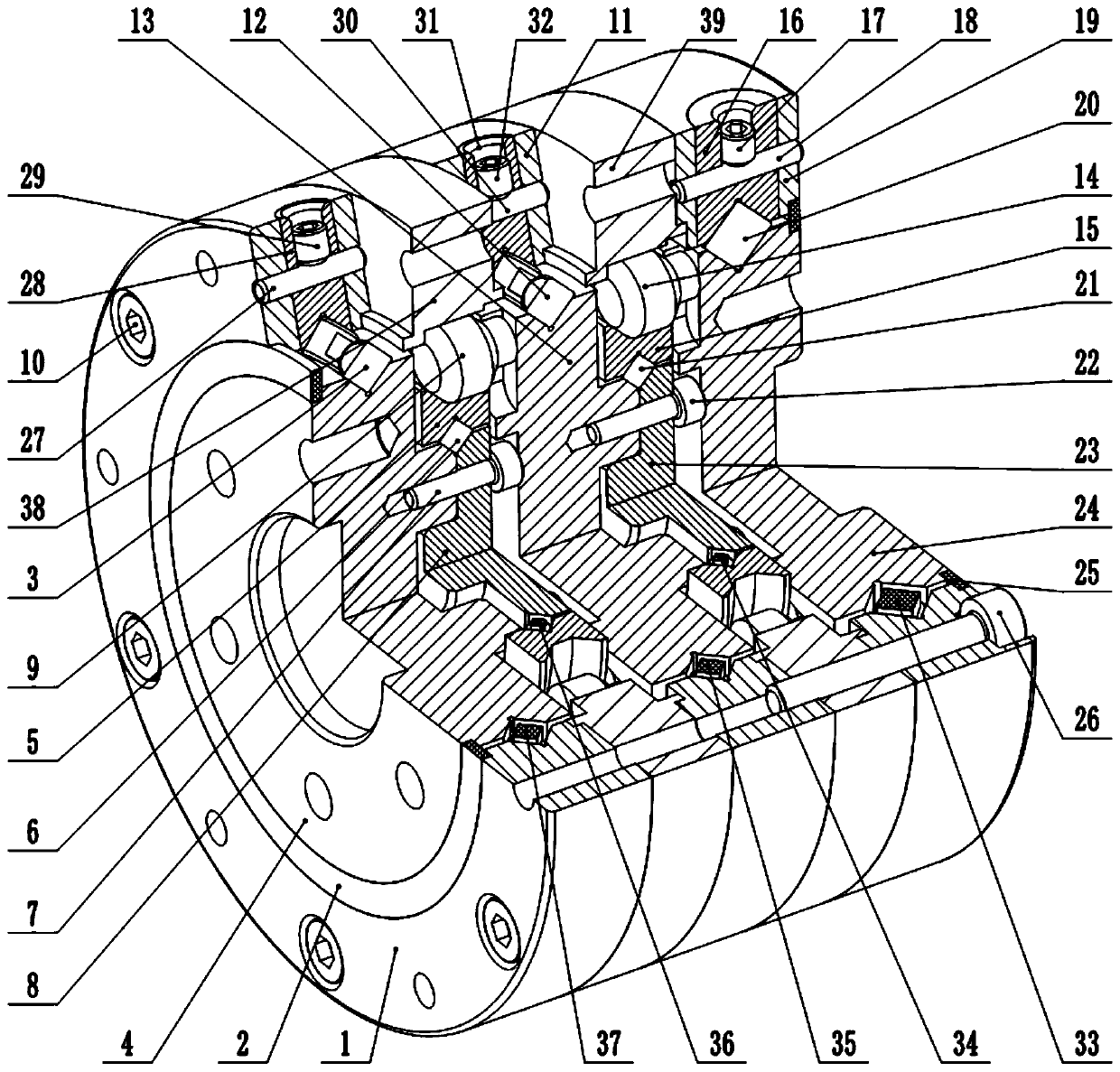
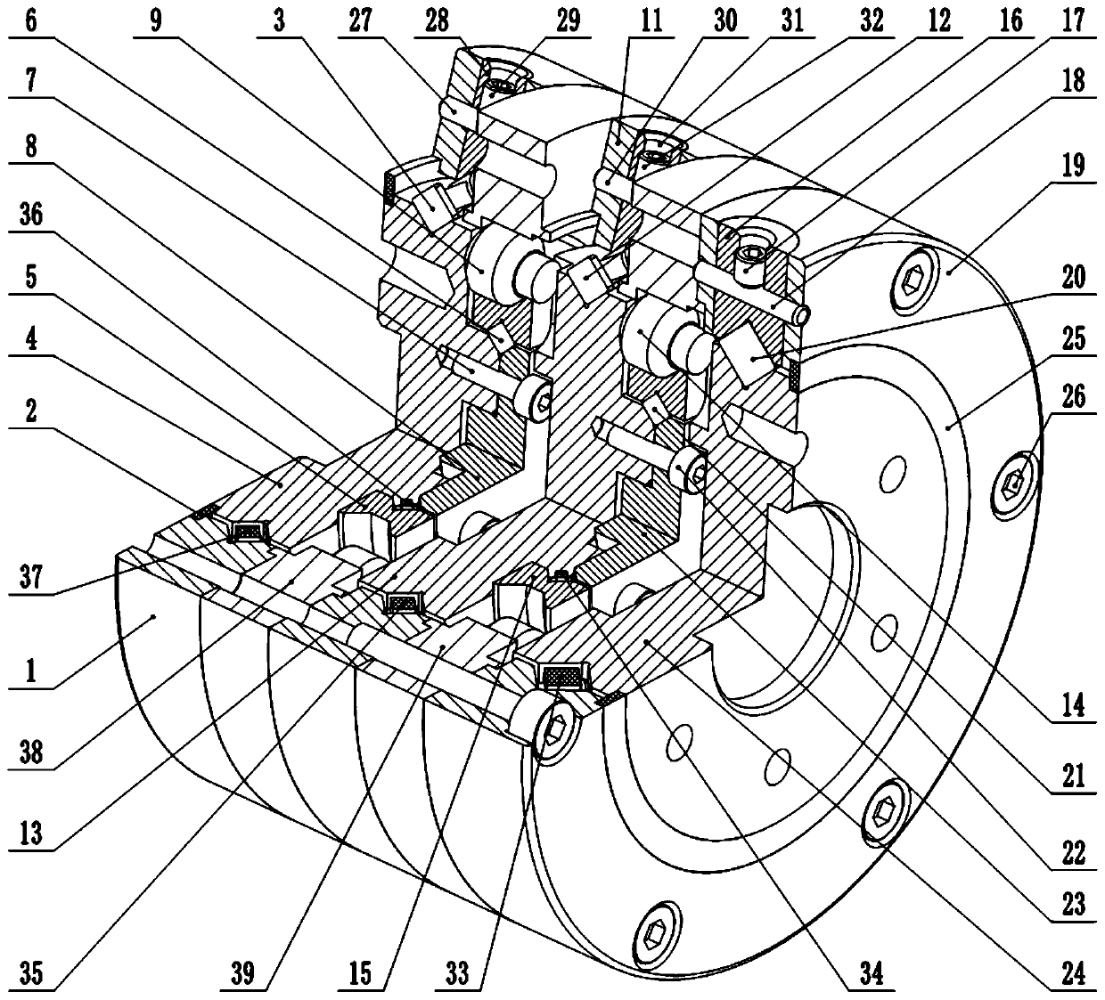
[0071] Such as Figure 9 As shown, a small double-stage hammer roller movable gear reducer is designed for a certain application, as the preferred embodiment 2 of the present invention, its overall size is, outer diameter φ70mm, length 48mm; this structure will be the embodiment The primary center wheel 38 and secondary center wheel 39 in 1 are split and recombined into the first housing 1, the second housing 11 and the third housing 19. The theoretical parameters of the primary and secondary transmissions are shown in Table 2.

[0072] Table 2 Embodiment 2 Structural Theoretical Parameter Table

[0073]

[0074]

[0075] Among them, the cone half-angles of the first cone surface 901 and the second cone surface 903 of the first-stage hammer roller movable tooth 9 and the second-stage hammer roller movable tooth 14 are both 60°, and the angle can be selected according to the actual stress situation. Certainly.

[0076] In particular, when the first-stage center wheel and ...


PUM


Abstract

The invention discloses a small double-stage hammer-shaped pin roller oscillating tooth speed reducer. The small double-stage hammer-shaped pin roller oscillating tooth speed reducer mainly comprisesa first shell body, an input shaft, a primary shock diffuser inner ring, a primary shock diffuser outer ring, primary hammer-shaped pin roller oscillating teeth, a second shell body, a primary oscillating tooth frame, secondary hammer-shaped pin roller oscillating teeth, a secondary shock diffuser outer ring, a secondary shock diffuser inner ring, a third shell body, a secondary oscillating toothframe, a primary center wheel, a secondary center wheel and the like. The device draws the beneficial effects of a pin roller oscillating tooth speed reducer and a steel ball oscillating tooth speed reducer, five composite integrated specially-made crossed roller bearings are adopted, and the whole machine has a smaller length-diameter ratio, a lower weight and a lower machining and manufacturingdifficulty, and meanwhile has higher structural rigidity, higher bearing capacity and higher transmission efficiency. The speed reducer can be subjected to parameterization, miniaturization and serialization design, can be applied to multiple fields, and can assist rapid rise of the industries such as intelligent manufacturing and 5G communication.

Description

technical field [0001] The invention relates to a movable tooth transmission device, in particular to a small double-stage hammer roller movable tooth reducer. Background technique [0002] The known reducers on the market are all evolved from gears. The three common types are planetary reducers, RV reducers and harmonic reducers. There are too many components, the manufacturing is too complicated, and the precision and torque are not enough. Among them, although the RV reducer and the harmonic reducer have high precision, the accuracy retention and rigidity are not enough, the torque is small, and the service life is not long. With the rapid rise of smart manufacturing, smart home, and 5G communication industries, miniaturization and light weight will become a new development trend of precision reducers. Transmission devices used in robots, precision machine tools, aerospace and other precision servo mechanisms require high transmission accuracy, high transmission stiffnes...

Claims


Application Information

Patent Timeline
Patent Type & Authority Applications(China)
IPC IPC(8): F16H49/00F16H57/08F16H57/021F16H57/023
CPCF16H49/001F16H57/021F16H57/023F16H57/08F16H2057/0087F16H2057/02086
Inventor 许立忠闫济东
Owner YANSHAN UNIV
Why Eureka
Try Eureka