Novel horizontal drying machine

A dryer and horizontal technology, applied in the field of new horizontal dryers, can solve the problems of uneven moisture content of the catalyst, unqualified product quality, and drying of the catalyst to less than 0.3%, so as to avoid uneven heating and improve quality. Effect

Inactive Publication Date: 2020-04-21
NINGXIA JINHAI CHUANGKE CHEM TECH
View PDF7 Cites 2 Cited by
  • Summary
  • Abstract
  • Description
  • Claims
  • Application Information

AI Technical Summary

Problems solved by technology

[0003] The purpose of the present invention is: in order to solve the problem that after the catalyst is added into the drying tank, the catalyst is fixed in the drying tank, and the drying rate of the catalyst is difficult to keep consistent during the process of introducing hot air, resulting in the fact that the hot air cannot pass through the material layer evenly. It is easy to short-circuit, so that the moisture content of the catalyst in the drying tank is uneven; or when the air humidity is high in summer, the moisture content of the hot air itself is high, so it is difficult to dry the moisture of the catalyst to below 0.3% by using hot air. Problems leading to unqualified product quality, providing a new type of horizontal dryer

Method used


Image

  • Novel horizontal drying machine
  • Novel horizontal drying machine
  • Novel horizontal drying machine

Examples


Embodiment 1

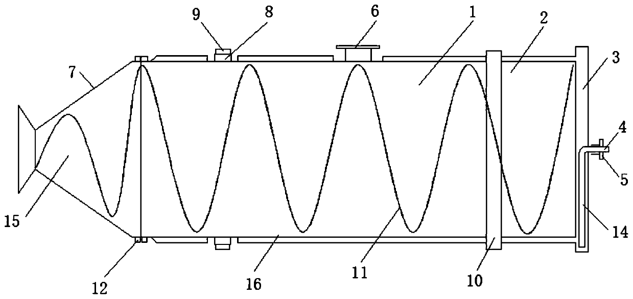
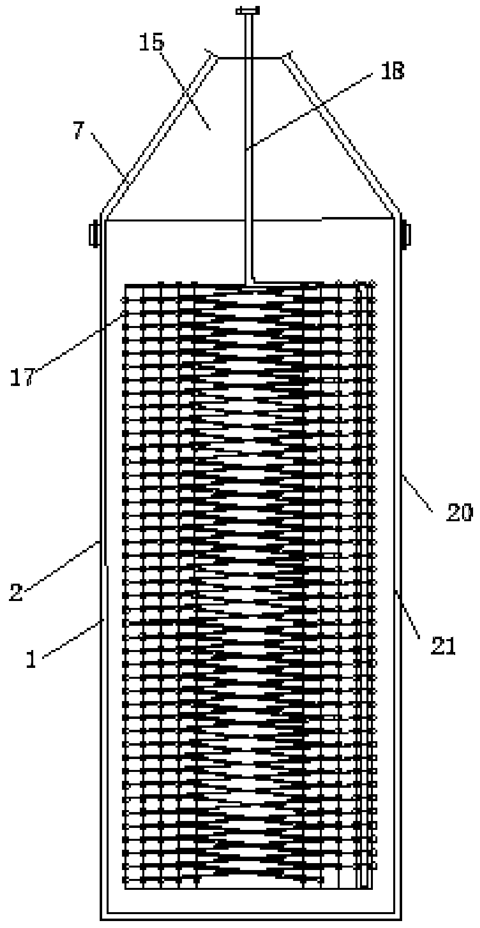
[0024] As a preferred embodiment of the present invention, the number of titanium plate spiral bands 11 is four groups, and both sides of the inner wall of the tank body 2 are evenly provided with multiple sets of spiral band fixing blocks 13, and the titanium plate spiral bands 11 are all passed through the spiral bands. The fixed block 13 is fixedly connected to the inside of the tank body 2, the side of the conical titanium plate tank 7 close to the tank body 2 communicates with the tank body 2, and the outer sides of the tank body 2 and the conical titanium plate tank 7 are provided with flanges 12 , and the tank body 2 is detachably connected to the conical titanium plate tank 7 through the mutual cooperation of the flange plate 12 and the fastening bolts.

[0025] This new type of horizontal dryer better fixes and connects the titanium plate spiral belt 11 through the spiral belt fixing block 13, which is convenient for fixing the titanium plate spiral belt 11 inside the ...

Embodiment 2

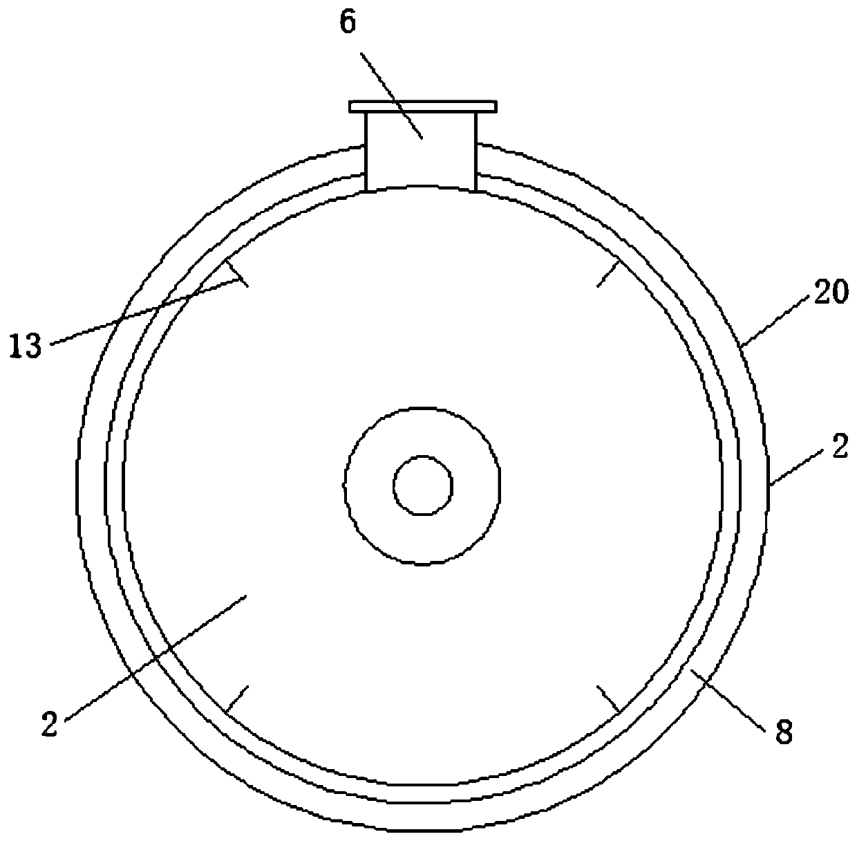
[0027] As a preferred embodiment of the present invention, the number of backing plates 8 is eight, and the first rolling belt 9 is fixedly connected with the tank body 2 through the backing plate 8, the number of the second rolling belts 10 is two groups, and the second The rolling belts 10 are all located on the side of the tank body 2 close to the cavity 3 .

[0028] This new type of horizontal dryer makes the fixing effect of the first rolling belt 9 and the tank body 2 better through the backing plate 8, and facilitates the tank body 2 in the rolling process by using the first rolling belt 9 and the second rolling belt 10 Play the role of support (the tank body 2 rolls under the action of external force, and the specific components and structure of rolling belong to the prior art, which will not be described in detail here), thereby improving the stability.

[0029] Example 2

[0030] As a preferred embodiment of the present invention, the material of the straight sectio...


PUM


Abstract

The invention discloses a novel horizontal drying machine, and belongs to the technical field of drying. The horizontal drying machine comprises a main machine body; a tank body is arranged on the outer side of the main machine body; a conical titanium-plate tank is arranged on one side of the tank body; the tank body comprises an outer casing and an inner casing; a cavity is arranged between theouter casing and the inner casing; a liquid outlet pipe penetrating to one side of the tank body is arranged in the cavity; and a liquid outlet is formed in one side of the liquid outlet pipe. According to the horizontal drying machine, the rotating drying manner is adopted, a first rolling belt and a second rolling belt are used as supporting points, the tank body rotates between the first rolling belt and the second rolling belt, a rotating barrel plays the stirring and guiding effects on inside steam during rotation by the aid of a titanium-plate spiral belt, the condition of non-uniform moisture caused by non-uniform heating of a catalyst is avoided, the steam coil pipe heating manner is adopted, the inside of the tank body is thoroughly isolated from the outside air, and the influenceof the high air humidity in summer on catalyst drying is avoided.

Description

technical field [0001] The invention relates to the technical field of drying, in particular to a novel horizontal dryer. Background technique [0002] The existing drying equipment is a cylindrical drying tank with a cone at the bottom. The catalyst is added to the drying tank and then hot air at 130°C is introduced to dry the wet catalyst and control the moisture to below 0.3%, but there are the following disadvantages: One is that after the catalyst is added to the drying tank, the catalyst is fixed in the drying tank, and it is difficult to keep the drying rate of the catalyst consistent during the process of introducing hot air, which leads to the fact that the hot air cannot pass through the material layer evenly, and it is easy to short circuit, thus making The moisture content of the catalyst in the drying tank is uneven; second, when the air humidity is high in summer, the moisture content of the hot air itself is high, so it is difficult to dry the moisture of the ...

Claims


Application Information

Patent Timeline
Patent Type & Authority Applications(China)
IPC IPC(8): F26B11/06F26B23/10F26B25/04F26B25/16
CPCF26B11/0404F26B23/10F26B25/04F26B25/16
Inventor 李玉强
Owner NINGXIA JINHAI CHUANGKE CHEM TECH
Why Eureka
Try Eureka