Fundus image macular center positioning method and device, electronic equipment and storage medium

A fundus image and macular center technology, applied in the field of medical image processing, can solve problems such as low timeliness, poor robustness, and inability to effectively locate, and achieve the effect of eliminating dependence

Pending Publication Date: 2020-04-21
PING AN TECH (SHENZHEN) CO LTD
View PDF0 Cites 14 Cited by
  • Summary
  • Abstract
  • Description
  • Claims
  • Application Information

AI Technical Summary

Problems solved by technology

[0003] However, the macular center positioning method based on fundus images completely depends on the positioning of the optic disc center. Once the optic disc center positioning fails, the macular center cannot be effectively located, and the calculation complexity is high, the timeliness is low, and the robustness is poor.
Although the macular center location method based on deep neural network does not depend on the location of the optic disc center, the macula is easily affected by the lesion area, image quality and atrophy area, so the macular area cannot be successfully detected and cannot be effectively located.

Method used


Image

  • Fundus image macular center positioning method and device, electronic equipment and storage medium
  • Fundus image macular center positioning method and device, electronic equipment and storage medium
  • Fundus image macular center positioning method and device, electronic equipment and storage medium

Examples


Embodiment 1

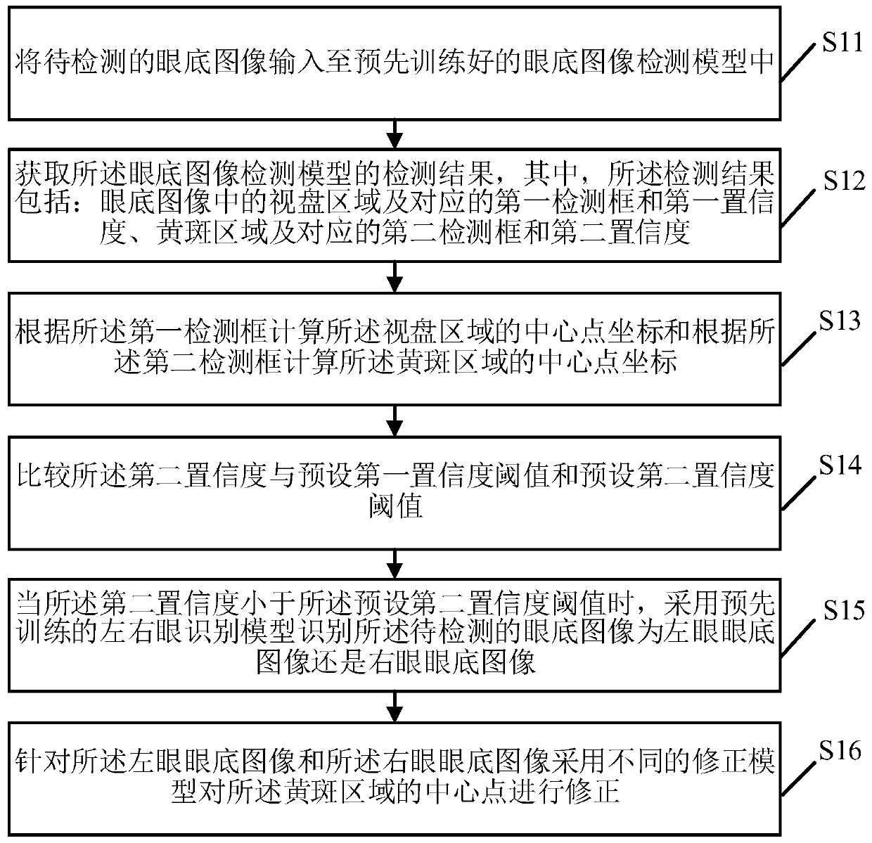
[0063] figure 1 It is a flow chart of the method for locating the center of the macula in the fundus image provided by Embodiment 1 of the present invention. According to different requirements, the execution sequence in the flow chart can be changed, and some steps can be omitted.

[0064] S11, input the fundus image to be detected into the pre-trained fundus image detection model.

[0065] Fundus images are images taken by eye detection equipment for diagnosing eye lesions. The fundus refers to the tissue at the back of the eyeball, including the retina, optic disc, macula, and central retinal artery and vein. Therefore, the fundus image to be detected includes the macula and the macular area formed around it, the retina and its surrounding areas. The optic disc area formed.

[0066] The fundus image detection model is obtained by using sample images of known locations of feature regions for training, the input is a fundus image, and the output is a fundus image marked wi...

Embodiment 2

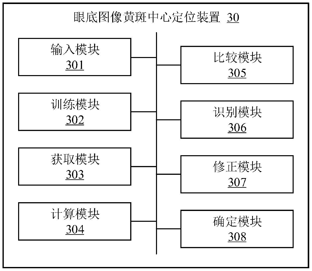
[0148] image 3 It is a structural diagram of a fundus image macular center positioning device provided by Embodiment 2 of the present invention.

[0149] The fundus image macular center positioning device 30 runs in electronic equipment, which can solve the problem of macular area detection failure due to image quality, lesion occlusion, etc. in the macular positioning method based on deep learning, and can eliminate the traditional method of macular center positioning. Dependence on the centralization of the optic disc. Such as image 3 As shown, the fundus image macular center positioning device 30 may include: an input module 301 , a training module 302 , an acquisition module 303 , a calculation module 304 , a comparison module 305 , an identification module 306 , a correction module 307 and a determination module 308 .

[0150] The input module 301 is used for inputting the fundus image to be detected into a pre-trained fundus image detection model.

[0151] Fundus im...

Embodiment 3

[0234] Figure 4 It is a schematic diagram of the electronic device provided by Embodiment 3 of the present invention. The electronic device 40 includes a memory 401 , a processor 402 , a communication bus 403 and a transceiver 404 . The memory 401 stores program codes that can run on the processor 402 , such as a fundus image macular center positioning program. When the processor 402 executes the program code, the steps in the above embodiment of the method for locating the macular center of the fundus image are realized.

[0235] Exemplarily, the program code may be divided into one or more modules, and the one or more modules are stored in the memory 401 and executed by the processor 402 to complete the method. The one or more modules may be a series of computer program instruction segments capable of accomplishing specific functions, and the instruction segments are used to describe the execution process of the program code in the electronic device 40 . For example, the ...


PUM


Abstract

The invention provides a fundus image macular center positioning method and device, electronic equipment and a storage medium. The fundus image macular center positioning method comprises the steps that a fundus image to be detected is input into a fundus image detection model; obtaining a detection result of the fundus image detection model, wherein the detection result comprises an optic disc region and a corresponding first detection frame, a macular region and a corresponding second detection frame and confidence; calculating central point coordinates of the optic disk area according to the first detection frame and calculating central point coordinates of the macular area according to the second detection frame; and when the confidence coefficient is smaller than a preset confidence coefficient threshold, identifying whether the fundus image to be detected is a left eye fundus image or a right eye fundus image, and correcting the central point of the macular area by adopting different correction models. The problem of macular area detection failure caused by image quality, lesion shielding and the like in a macular positioning method based on deep learning is solved, and the dependence of macular center positioning and optic disc center positioning in a traditional method is eliminated.

Description

technical field [0001] The invention relates to the technical field of medical image processing, in particular to a method, device, electronic equipment and storage medium for locating the center of the macula in a fundus image. Background technique [0002] A large number of visual function cells are concentrated in the macula. If the lesion in the macular area is not detected and treated in time, the chance of blindness will be greatly increased. Therefore, accurate macular center positioning is of great significance for the diagnosis of retinopathy. In the prior art, there is a method for locating the center of the macula based on fundus images, which first locates the center of the optic disc, and then locates the center of the macula according to the center of the optic disc; or directly detects the macular region using a target detection model of a deep neural network. [0003] However, the macular center location method based on fundus images completely depends on the...

Claims


Application Information

Patent Timeline
Patent Type & Authority Applications(China)
IPC IPC(8): G06K9/00G06K9/32G06K9/46G06K9/62G06N3/04G06N3/08
CPCG06N3/08G06V40/197G06V40/193G06V40/18G06V10/464G06V10/25G06V2201/03G06N3/045G06F18/241G06T7/70G06T2207/30041G06T2207/20084G06V10/82G06V10/98G06T7/73G06V10/774G06V10/776G06T7/60G06T2207/20081
Inventor 李葛王瑞王立龙唐义君张萌高鹏
Owner PING AN TECH (SHENZHEN) CO LTD
Why Eureka
Try Eureka