Machine tool oil cooling system and control method thereof

A technology of oil cooling system and machine tool, applied in the direction of manufacturing tools, metal processing machinery parts, maintenance and safety accessories, etc. problems, to achieve the effect of improving temperature control accuracy, prolonging service life, and providing machining accuracy

Pending Publication Date: 2020-04-24
GREE ELECTRIC APPLIANCES INC
View PDF0 Cites 0 Cited by
  • Summary
  • Abstract
  • Description
  • Claims
  • Application Information

AI Technical Summary

Problems solved by technology

[0003] However, the temperature control accuracy of the existing machine tool oil cooling system is not high, because too much cooling oil bypass will lead to insufficient heat exchange of the refrigerant in the evaporator, causing the compressor to suck liquid, which will affect the reliable operation of the machine tool. Reduced service life of machine tools

Method used


Image

  • Machine tool oil cooling system and control method thereof
  • Machine tool oil cooling system and control method thereof
  • Machine tool oil cooling system and control method thereof

Examples


Embodiment 1

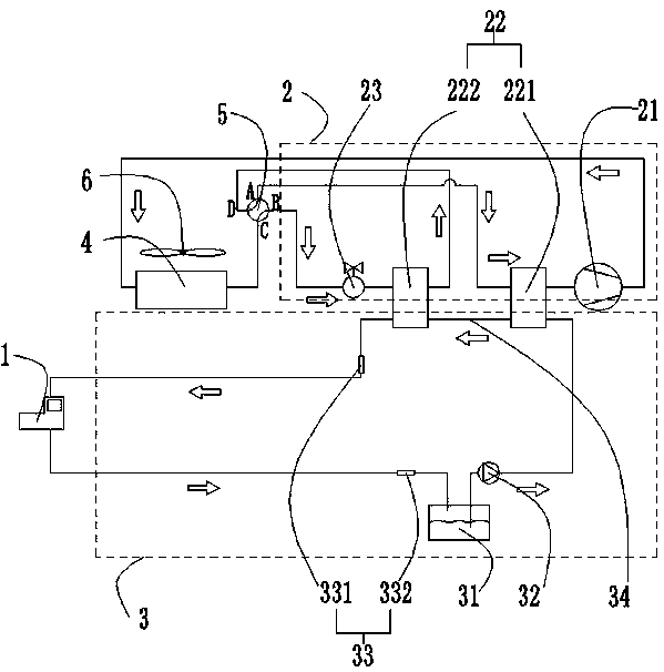
[0027] Such as Figure 1-2 As shown, the embodiment of the present invention provides a machine tool oil cooling system, including an organic machine tool 1, a refrigeration device 2, a cooling device 3, a first condenser 4, a hydraulic valve component 5 and a DC fan assembly 6, and one end of the machine tool 1 is connected to the refrigeration unit. The device 2 is connected, the other end is connected with the cooling device 3, the refrigeration device 2 is connected with the cooling device 3, one end of the hydraulic valve part 5 is connected with the refrigeration device 2, and the other end is connected with the first condenser 4, and the first condenser 4 is connected with the refrigeration device 2. The device 2 is connected, and the DC fan assembly 6 is fixed on one side of the first condenser 4, so that the machine tool can change the direction of the hydraulic valve part 5 and the speed adjustment of the DC fan assembly 6 during the working process, and change the co...

Embodiment 2

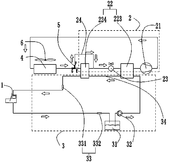
[0039] Such as Figure 3-4 As shown, the embodiment of the present invention provides a machine tool 1 oil cooling system, including an organic machine tool 1, a refrigeration device 2, a cooling device 3, a first condenser 4, a hydraulic valve component 5 and a DC fan assembly 6, and one end of the machine tool 1 is connected to the The refrigeration device 2 is connected, the other end is connected with the cooling device 3, the refrigeration device 2 is connected with the cooling device 3, one end of the hydraulic valve part 5 is connected with the refrigeration device 2, and the other end is connected with the first condenser 4, and the first condenser 4 is connected with the The refrigeration device 2 is connected, and the DC fan assembly 6 is fixed on one side of the first condenser 4, so that the machine tool can change the direction of the hydraulic valve part 5 and the speed adjustment of the DC fan assembly 6 during the working process, and change the cooling oil in t...


PUM


Abstract

The invention provides a machine tool oil cooling system. The cooling system comprises a machine tool, a refrigerating device, a cooling device, a first condenser, a hydraulic valve part and a direct-current fan assembly. One end of the machine tool is connected with the refrigerating device; the other end is connected with the cooling device; the refrigerating device is connected with the coolingdevice; one end of the hydraulic valve part is connected with the refrigerating device; the other end of the condenser is connected with the first condenser, the first condenser is connected with therefrigerating device, and direct-current fan assembly is fixed to one side of the first condenser. According to the machine tool oil cooling system, the temperature control precision of cooling oil can be effectively improved, the machining precision of machine tool equipment is improved, meanwhile, the reliability of the cooling equipment is improved, and the service life of the machine tool isprolonged.

Description

technical field [0001] The invention relates to the technical field of cooling control, in particular to a machine tool oil cooling system and a control method thereof. Background technique [0002] In modern manufacturing, machine tools are indispensable equipment, such as CNC (Computer Numerical Control, digital control machine tools), grinding machines, wire cutting machine tools and so on. When the machine tool is working, the high-speed operation of the cutting tool and the spindle will generate a lot of heat, which will cause thermal deformation of the guide rail and the spindle of the machine tool, thereby reducing the machining accuracy of the workpiece and reducing the life of the tool and the spindle. Therefore, there is a need to cool the machine tool. The role of machine tool coolers such as oil coolers (also known as oil coolers) is to effectively reduce the heat generated by machine tool cutting. [0003] However, the temperature control accuracy of the exist...

Claims


Application Information

Patent Timeline
Patent Type & Authority Applications(China)
IPC IPC(8): B23Q11/12
CPCB23Q11/126B23Q11/127
Inventor 陈桂福
Owner GREE ELECTRIC APPLIANCES INC
Why Eureka
Try Eureka