An energy-saving variable frequency double-disc friction press and its working method

A friction press, energy-saving technology, applied in the direction of the driving device of presses, stamping machines, forging presses, etc., can solve the problem of affecting the dynamic precision of friction presses, the quality of stamping products, the low effective utilization of disc energy, flywheels and friction To solve the problem of rated slip rate, improve the service life and reduce the impact force

Active Publication Date: 2022-07-12
TAICANG HONGDA JUNMENG NEW MATERIAL
View PDF0 Cites 0 Cited by
  • Summary
  • Abstract
  • Description
  • Claims
  • Application Information

AI Technical Summary

Problems solved by technology

However, the traditional double-disc friction press has the following disadvantages: 1) Because the motor of the double-disc friction press is always working, especially in the non-strike auxiliary intermittent time, the output of the motor is basically useless work, and the effective utilization of disc energy is very low. Low power consumption and energy consumption; 2) The motor needs to drive the friction disc to rotate at high speed all the time, and the flywheel needs to change the direction of rotation during a cycle, and the flywheel and the friction disc will slip severely during the commutation, which not only reduces the transmission efficiency , also exacerbated the wear of the friction belt; 3) The vibration of the friction press during production operations will affect the dynamic accuracy of the friction press and the quality of stamped products, and will also reduce the actual production efficiency and the service life of the mold

Method used


Image

  • An energy-saving variable frequency double-disc friction press and its working method
  • An energy-saving variable frequency double-disc friction press and its working method
  • An energy-saving variable frequency double-disc friction press and its working method

Examples


Embodiment 1

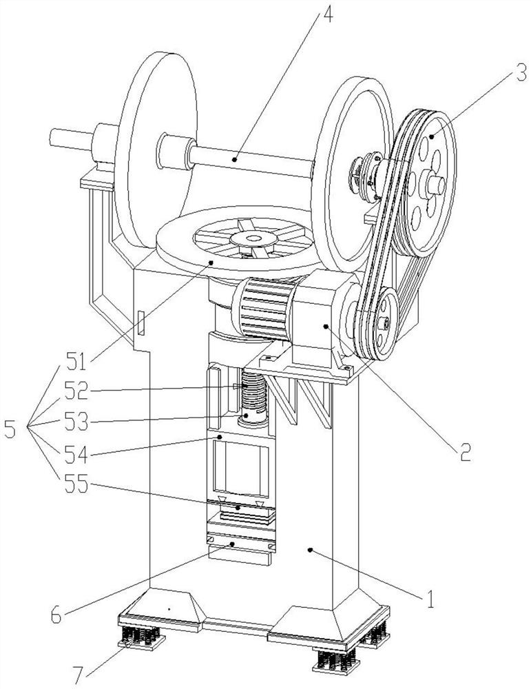
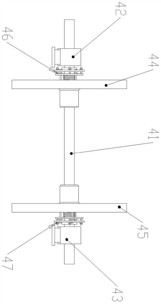
[0035] like figure 1 Shown is a perspective view of the present invention, including a frame base 1, a power structure 2, a belt drive 3, a disc friction drive structure 4, a flywheel moving structure 5, a fixed die 6 and a shock absorbing structure 7, and the power structure 2 is arranged in the The frame base 1 is connected with the disc friction transmission structure 4 through the belt drive 3, the flywheel moving structure 5 is arranged on the frame base 1 and is located under the disc friction transmission structure 4, and the fixed die 6 is arranged on the frame base 1 The upper part is located directly below the flywheel moving structure 5, and the shock absorbing structure 7 is arranged directly below the frame base 1; figure 2 Shown is the front view of the disc friction transmission structure 4, including the main shaft 41, the first bearing seat 42, the second bearing seat 43, the first friction wheel 44, the second friction wheel 45, and the first friction wheel ...


PUM


Abstract

An energy-saving variable-frequency double-disc friction press and its working method, comprising a frame base, a power structure, a belt drive, a disc friction drive structure, a flywheel moving structure, a fixed die and a damping structure, and the power structure is arranged on the machine. The frame base is connected with the disc friction transmission structure through the belt drive. The flywheel moving structure is arranged on the frame base and is located below the disc friction transmission structure. The shock absorbing structure is arranged directly below the frame base. The forging raw material is placed in the fixed die, the power structure drives the disc friction transmission structure to rotate through the belt drive, and the flywheel moving structure moves to the fixed die structure under the action of friction pressure to strike. Each structure cooperates to complete the forging work of the double-disc friction press.

Description

technical field [0001] The invention relates to the field of double-disc friction presses, in particular to an energy-saving variable-frequency double-disc friction press and its working mode. Background technique [0002] The double-disc friction press is a kind of screw press that adopts the friction drive mode. It uses the contact transmission between the flywheel and the friction disc, and works by the relative motion principle of the screw and the nut. Because of its versatility in use, and the advantages of simple structure, installation, operation and auxiliary equipment and low price, it is widely used in stamping workshops, forging workshops and die forging workshops in machinery manufacturing, automobile, tractor and aviation industries. are widely used. However, the traditional double-disc friction press has the following shortcomings: 1) Because the motor of the double-disc friction press is always working, especially in the non-strike auxiliary intermittent tim...

Claims


Application Information

Patent Timeline
Patent Type & Authority Patents(China)
IPC IPC(8): B30B1/22B30B15/00B21J9/18
CPCB30B1/22B30B15/0076B21J9/18Y02P70/10
Inventor 严建忠
Owner TAICANG HONGDA JUNMENG NEW MATERIAL
Why Eureka
Try Eureka