Water level monitoring device and putting device
A technology of water level monitoring device and dispenser, which is applied to washing devices, textiles and papermaking, and other washing machines, etc. It can solve the problems that do not involve the coordination of floats, etc., and achieve the effects of easy processing, convenient installation, and space saving
- Summary
- Abstract
- Description
- Claims
- Application Information
AI Technical Summary
Problems solved by technology
Method used
Image
Examples
Embodiment 1
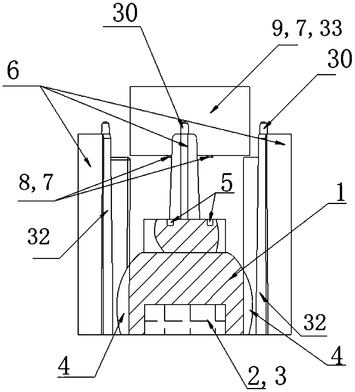
[0036] Such as figure 1 As shown, this embodiment provides a water level monitoring device. The water level monitoring device mainly includes a float 1 that can be suspended in the liquid and a fixed position-limiting structure for restricting the movement of the float 1 to rise and fall with the liquid level. In this embodiment, the water level monitoring device is installed in the chamber where the liquid is stored, and the position-limiting structure that limits the movement of the float 1 is fixed on the wall of the chamber.
[0037] Depend on figure 1 It can be seen that in this embodiment, the float 1 is a column structure whose cross-section is circular and whose radial dimension is constantly changing. The maximum radial dimension of the float 1 is in the middle, and the radial dimension of the float 1 starts from the maximum The positions are gradually reduced upwards and downwards. figure 1It can be clearly seen in the figure that the upper part of the float 1 has...
Embodiment 2
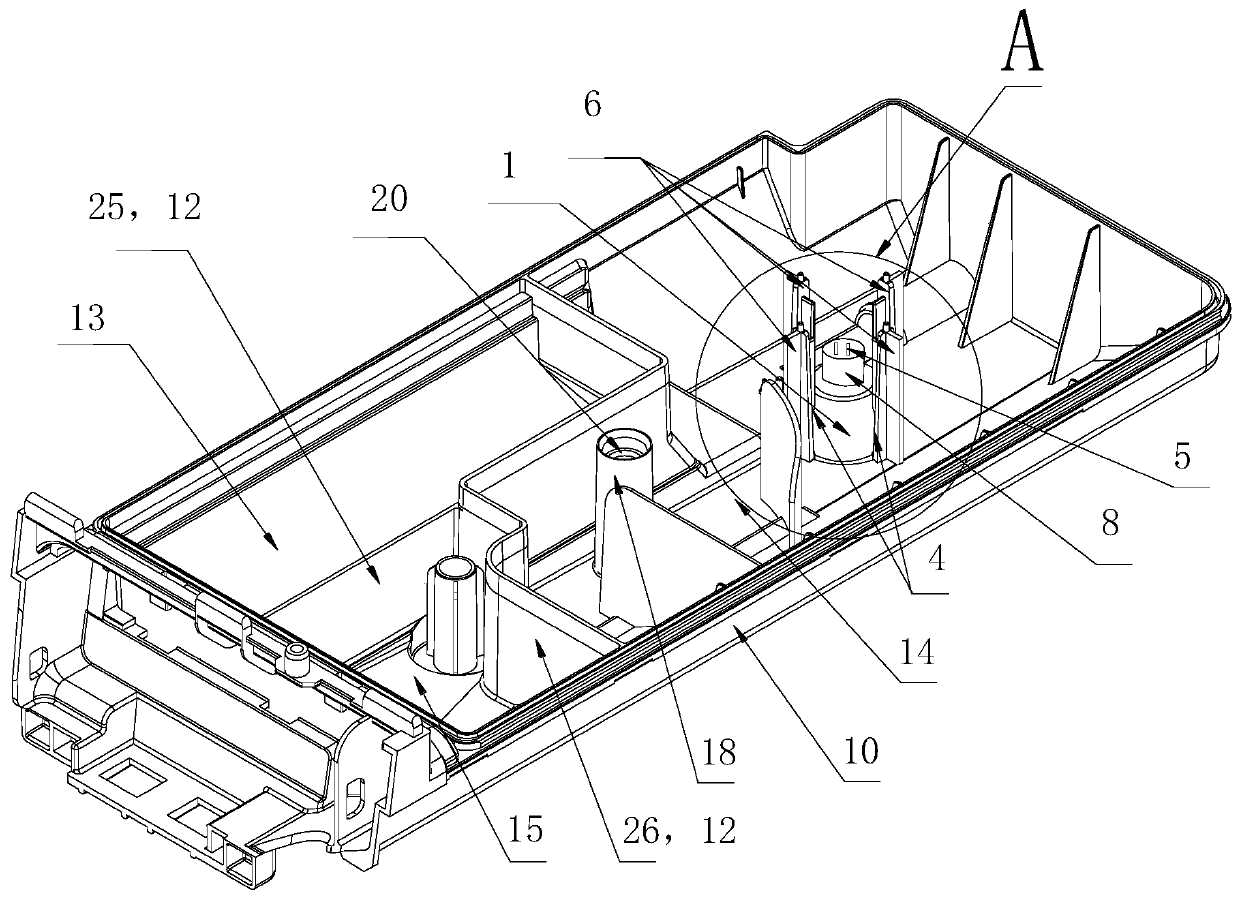
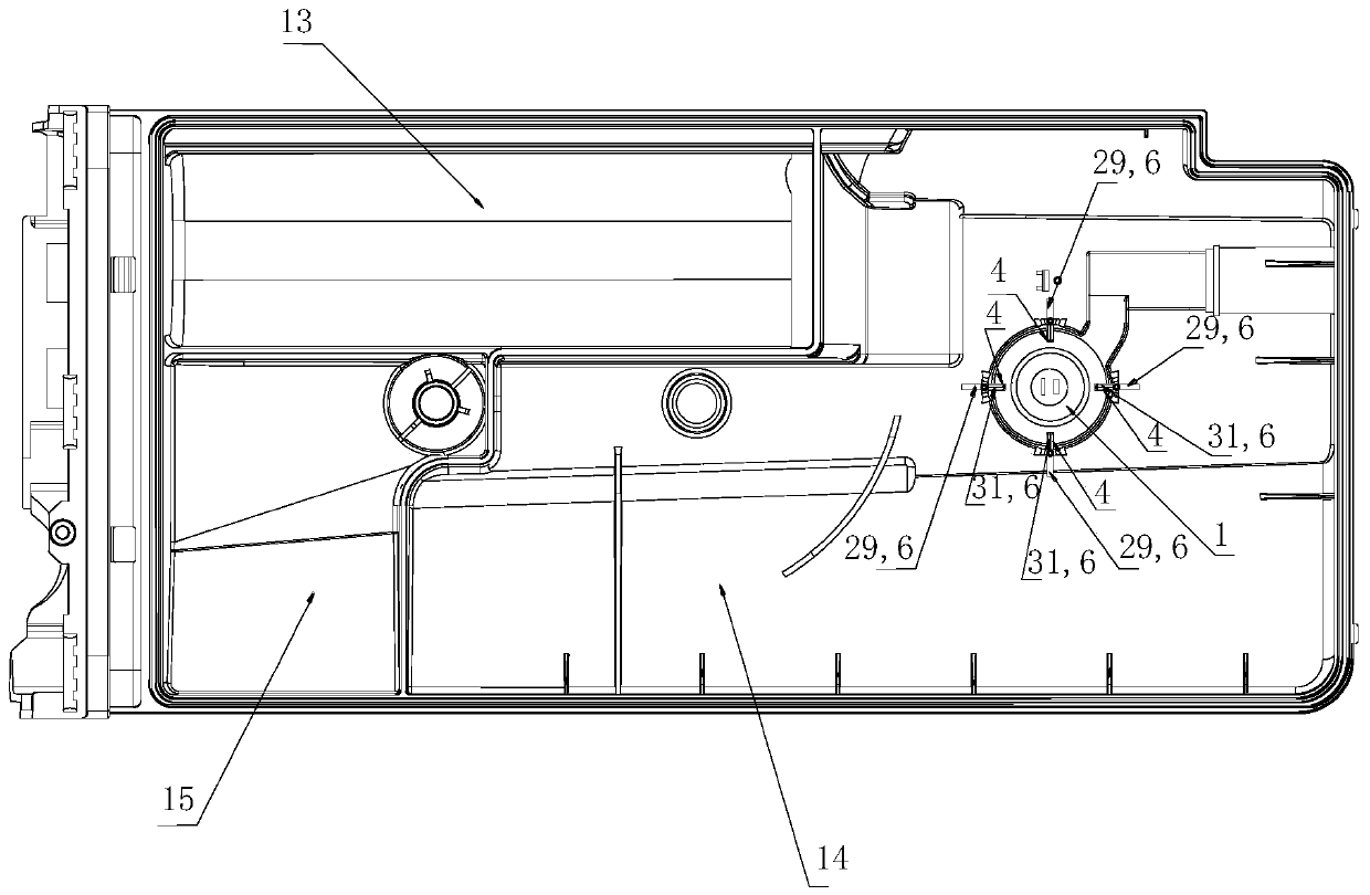
[0049] Such as Figure 2-5 As shown, this embodiment provides a dispenser. The dispenser includes a drop box 10 and a drop cover 11 that is fastened with the drop box 10. A plurality of separating ribs 12 are arranged in the drop box 10, and the drop box 10 is separated into a washing powder cavity 13, a detergent cavity 14, and a flexible cavity. Agent chamber 15. And a float monitoring water level device as described in Embodiment 1 is set in any chamber in the dispenser, and the float monitoring water level device can monitor the water level in the dispenser box 10 at any time in the dispenser. The first spacer rib 6 of the water level monitoring device is fixed on the bottom wall 16 of the drop-in box, and the second spacer rib 7 of the water level monitoring device is fixed on the bottom wall 17 of the drop-in cover. A sensing device opposite to the water level monitoring device for sensing the height change of the float 1 is arranged at the bottom of the dropping box 1...
Embodiment 3
[0053] This embodiment proposes a dispenser with a water guiding device on the basis of the dispenser proposed in Embodiment 2. Such as figure 2 , 5 , Shown in 6, the lower end structure 18 of the water guide is set in the detergent chamber 14 respectively, and the upper end structure 19 of the water guide combined with the lower end structure 18 of the water guide is set at the corresponding position on the throwing cover 11. That is, when the throwing cover 11 and the throwing box 10 are combined, the upper structure 19 of the water guiding device is combined with the lower structure 18 of the water guiding device to form the water guiding device.
[0054]In this embodiment, when the upper end structure 19 of the water guiding device is combined with the lower end structure 18 of the water guiding device, a receiving groove 23 will be formed, and a sealing ring 24 is installed in the receiving groove 23 to seal the upper end structure 19 of the water guiding device and the...
PUM
 Abstract
Description
Claims
Application Information
 - R&D Engineer
- R&D Manager
- IP Professional
- Industry Leading Data Capabilities
- Powerful AI technology
- Patent DNA Extraction
Browse by: Latest US Patents, China's latest patents, Technical Efficacy Thesaurus, Application Domain, Technology Topic, Popular Technical Reports.
© 2024 PatSnap. All rights reserved.Legal|Privacy policy|Modern Slavery Act Transparency Statement|Sitemap|About US| Contact US: help@patsnap.com


