Anti-cavitation centrifugal pump and manufacturing method thereof

A technology for centrifugal pumps and pump casings, which is applied to parts, pumps, and pump components of elastic fluid pumping devices, and can solve cavitation unstable flow, blade channel distortion, and severe fluctuations in system flow and pressure, etc. problem, achieve the effect of reducing the unstable state, ensuring the installation accuracy and prolonging the service life

Active Publication Date: 2020-04-24
ZHEJIANG UNIV OF WATER RESOURCES & ELECTRIC POWER
View PDF6 Cites 0 Cited by
  • Summary
  • Abstract
  • Description
  • Claims
  • Application Information

AI Technical Summary

Problems solved by technology

When the inducer is used in a high-speed centrifugal pump, its working conditions often change during operation, and it is often accompanied by complex cavitation phenomena. The instability of the inlet flow field caused by backflow is considered to be an important reason for inducing rotating cavitation. , even when the inducer is running normally, its internal flow is more complicated due to the twisted blade flow path; when the inducer is cavitating during operation, it is easy to generate cavitation unstable flow phenomenon inside, and cavitation occurs, causing The severe fluctuation of the system flow and pressure will generate vibration and noise, which will seriously affect the stable operation of the pump body.

Method used


Image

  • Anti-cavitation centrifugal pump and manufacturing method thereof
  • Anti-cavitation centrifugal pump and manufacturing method thereof
  • Anti-cavitation centrifugal pump and manufacturing method thereof

Examples


Embodiment Construction

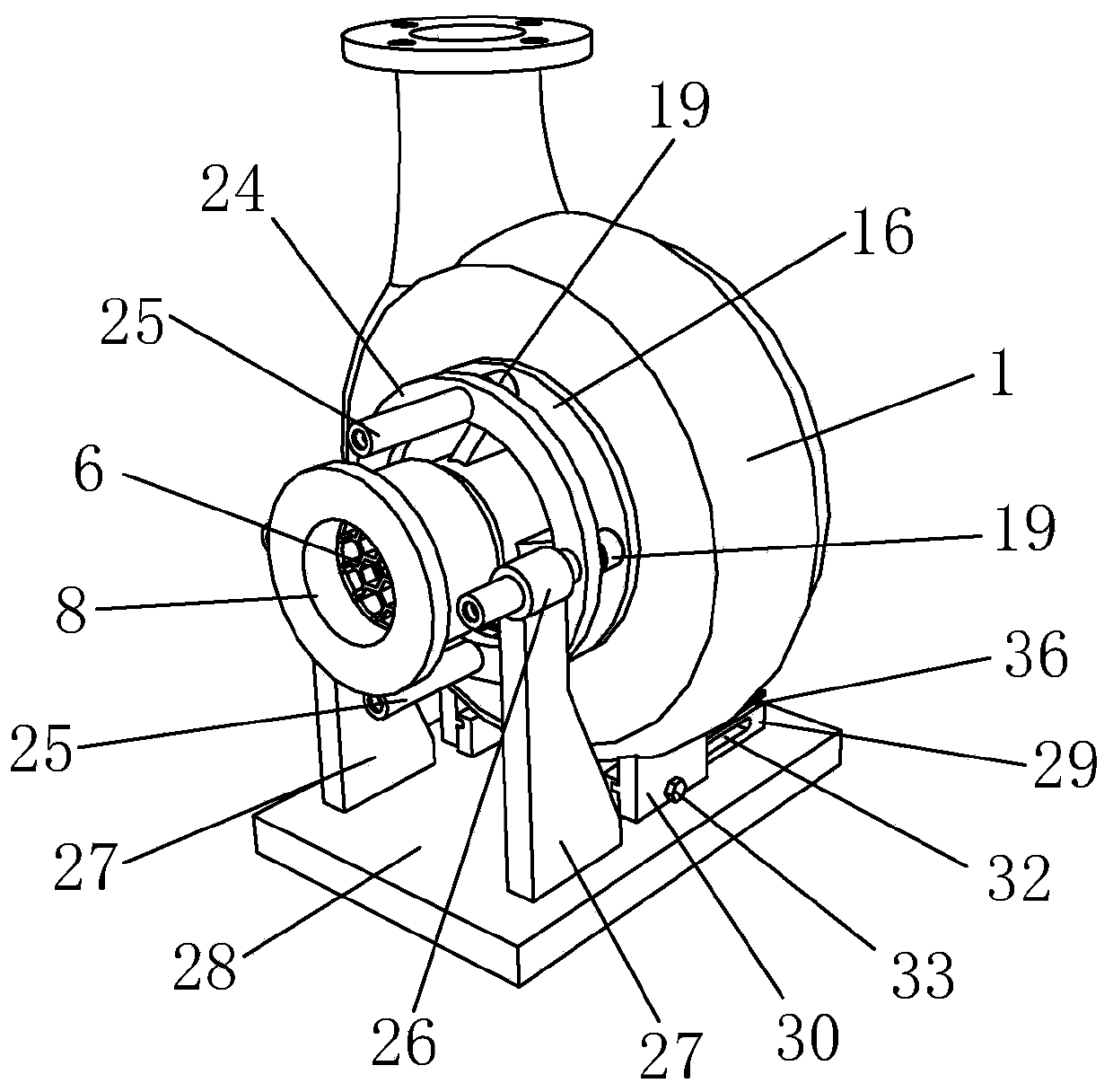
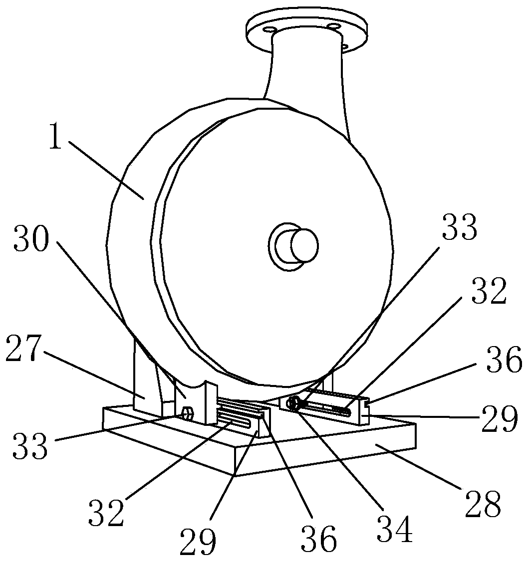
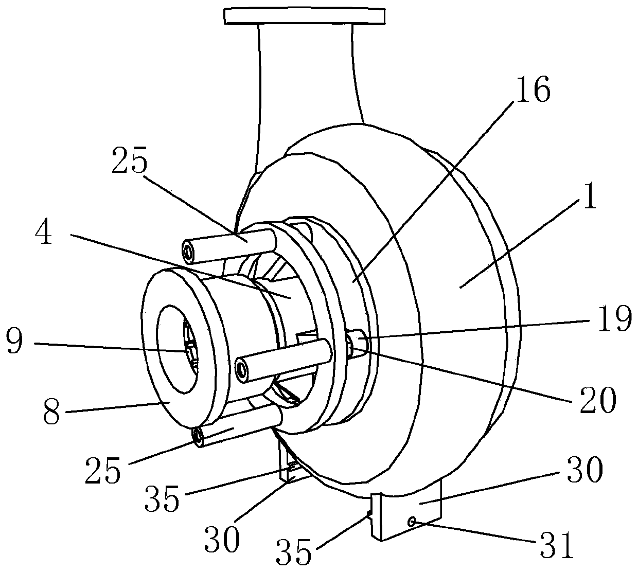
[0038] like Figure 1 to Figure 8 As shown, it is an anti-cavitation centrifugal pump of the present invention, comprising a pump casing 1, an impeller 2 and an inducer 3, the impeller 2 is arranged in the pump casing 1, the pump casing 1 is provided with a water inlet jacket 4, and the inducer 3 is arranged In the water inlet jacket 4, it is characterized in that: it also includes a support ring 5, the support ring 5 is provided with a deflector 6, the water inlet jacket 4 is provided with a groove 7, the support ring 5 is arranged in the groove 7, and the water inlet jacket 4. A clamping ring 8 is threadedly connected, the support ring 5 is provided with a clamping ring 9, and the clamping ring 8 clamps the clamping ring 9. By setting the deflector 6 on the water inlet jacket 4, the flow field of the water inlet jacket 4 can be made uniform, the backflow area can be reduced, the unstable state induced by rotating cavitation can be effectively reduced, and the stable operatio...


PUM


Abstract

The invention discloses an anti-cavitation centrifugal pump and a manufacturing method thereof. The device comprises a pump housing, an impeller and an induction wheel; the impeller is arranged in thepump housing; the pump housing is provided with a water inlet sleeve; and the induction wheel is arranged in the water inlet sleeve. The device further comprises a support ring; the support ring is provided with a guide member; the water inlet sleeve is provided with a groove; the support ring is arranged in the groove; the water inlet sleeve is in threaded connection to a clamping ring; a retainer ring is arranged on the support ring; and the retainer ring is clamped by the clamping ring. The manufacturing method manufactures the centrifugal pump by adopting eight steps of (a) machining preparation, (b) machining of the guide member, (c) machining of the pump housing, (d) assembly of a pump body, (e) machining of the water inlet sleeve, (f) mounting of the guide member, (g) total assembly and (h) testing. As the water inlet sleeve is provided with the guide member, the flow field of the water inlet sleeve can be uniform, the reflux region is reduced, the instable state induced by rotary cavitation is effectively reduced, the stable operation of the pump body is guaranteed, the manufacturing steps are optimized, the steps are simple, the manufacturing efficiency is high, and the implementation is easy.

Description

technical field [0001] The invention belongs to the technical field of centrifugal pumps, in particular to an anti-cavitation centrifugal pump and a manufacturing method thereof. Background technique [0002] High-speed centrifugal pumps are widely used in petrochemical, aerospace and other fields. Due to the high speed and low flow rate of high-speed centrifugal pumps, cavitation is easy to occur at the pump inlet, and cavitation occurs under low flow conditions. Therefore, high-speed The long-term safe and stable operation of the pump is the key to hydraulic design. At present, installing an inducer in a high-speed centrifugal pump has become a key technology to ensure that the pump obtains superior cavitation performance. When the inducer is used in a high-speed centrifugal pump, its working conditions often change during operation, and it is often accompanied by complex cavitation phenomena. The instability of the inlet flow field caused by backflow is considered to be ...

Claims


Application Information

Patent Timeline
Patent Type & Authority Applications(China)
IPC IPC(8): F04D1/00F04D29/42F04D29/44F04D29/62F04D29/66B23P15/00
CPCB23P15/00F04D1/00F04D29/426F04D29/445F04D29/628F04D29/669
Inventor 郭晓梅包志炎李祉宏杨世栋
Owner ZHEJIANG UNIV OF WATER RESOURCES & ELECTRIC POWER
Why Eureka
Try Eureka