Double-rod shearing mode magnetorheological damper

A magneto-rheological shock absorber and double-extrusion rod technology, which is applied in the direction of shock absorbers, shock absorbers, springs/shock absorbers, etc., can solve the problem of low body roll frequency, high manufacturing process difficulty, magnetorheological fluid Large dosage and other problems, to achieve the effect of reducing vehicle body vibration, novel overall structure and easy realization

Active Publication Date: 2020-04-24
NANJING FORESTRY UNIV
View PDF6 Cites 2 Cited by
  • Summary
  • Abstract
  • Description
  • Claims
  • Application Information

AI Technical Summary

Problems solved by technology

Considering that when the vehicle is turning, the frequency of vehicle body roll is low, and the telescopic valve magneto-rheological shock absorber cannot provide sufficient damping force to achieve effective roll control, which may lead to vehicle rollover accidents in severe cases
In addition, in order to ensure that the working area is always filled with magnetorheological fluid, it is necessary to set up an additional magnetorheological fluid compensation mechanism, which makes the consumption of magnetorheological fluid larger and the production cost of the shock absorber is relatively high
For example, in the application text of the patent application number 201910623043.8, a shear mode magnetorheological shock absorber is disclosed. The manufacturing process of the magnetorheological shock absorber with this structure is relatively difficult, the cost is also high, and additional The magnetorheological fluid compensation mechanism and other deficiencies

Method used


Image

  • Double-rod shearing mode magnetorheological damper
  • Double-rod shearing mode magnetorheological damper

Examples


Embodiment Construction

[0031] The following will clearly and completely describe the technical solutions in the embodiments of the present invention with reference to the accompanying drawings in the embodiments of the present invention. Obviously, the described embodiments are only some, not all, embodiments of the present invention. Based on the embodiments of the present invention, all other embodiments obtained by persons of ordinary skill in the art without making creative efforts belong to the protection scope of the present invention.

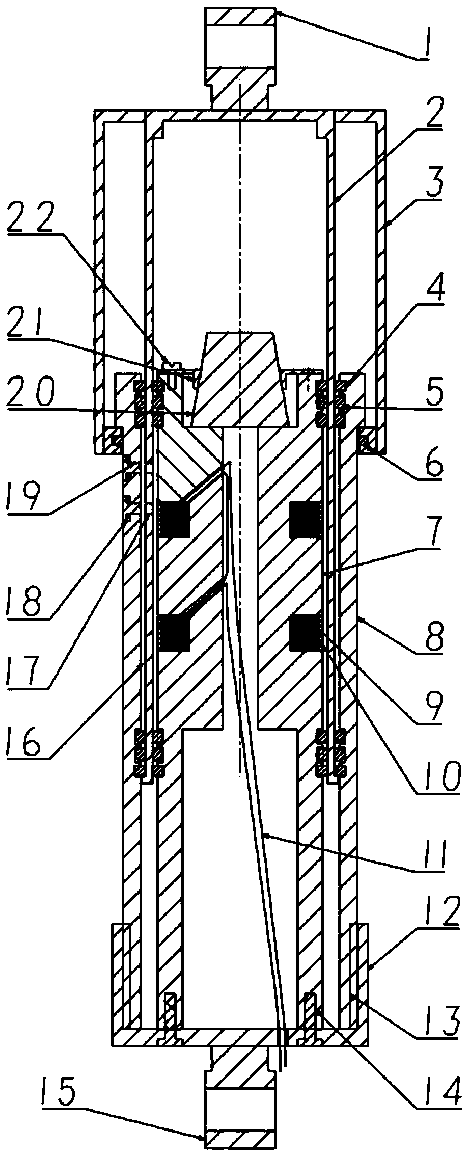
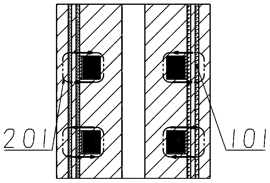
[0032] Such as Figures 1 to 2 As shown, the main structure of the double-rod shear mode magneto-rheological shock absorber of the present invention consists of: upper suspension ring 1, telescopic cylinder 2, dust cover 3, guide ring 4, sealing ring 5, felt 6, and inner cylinder 7 , Outer cylinder 8, coil 9, magnetic isolation ring 10, lower end cover 12, lower ring 15, buffer block 20, upper end cover 21 and other components. Wherein: the inner cylinder 7 a...


PUM


Abstract

The invention discloses a double-rod shearing mode magnetorheological damper. The magnetorheological damper comprises an inner cylinder, an outer cylinder and a telescopic cylinder positioned betweenthe inner cylinder and the outer cylinder; gaps are respectively reserved between the telescopic cylinder and the inner cylinder and between the telescopic cylinder and the outer cylinder; sealing rings are respectively arranged in the gaps at an interval; the gaps between the telescopic cylinder and the inner cylinder and between the telescopic cylinder and the outer cylinder are sealed through the sealing rings to further form a closed working chamber; the working chamber is filled with magnetorheological fluid; the telescopic cylinder can reciprocate in the magnetorheological fluid along the working chamber; a coil is wound on the outer wall of the section, located in the working chamber, of the inner cylinder; a magnetic field is generated after the coil is electrified; and the magnetic field acts on the magnetorheological fluid in the working chamber. According to the double-rod shearing mode magnetorheological damper, damping force is generated through a shearing mode, so that the magnetorheological damper has the obvious low-speed large damping characteristic. When a vehicle turns, quite large anti-turning damping force can be provided, so that tipping of the vehicle body iseffectively inhibited, operation stability of the vehicle is improved, the passing speed at curves is improved, and smoothness is improved.

Description

technical field [0001] The invention relates to a double-extruded rod shear mode magneto-rheological shock absorber, which belongs to the field of auto parts and vibration and noise reduction. Background technique [0002] Magnetorheological fluid is a material whose rheological properties such as viscosity and plasticity change sharply under the action of an external magnetic field. A controllable yield strength is produced, and this change is reversible. By changing the magnitude of the current, the rheological properties of the magnetorheological fluid can be effectively controlled. According to this principle, a magnetorheological shock absorber with continuously adjustable damping force can be designed. [0003] At present, the common magnetorheological shock absorbers are mostly telescopic valve magnetorheological shock absorbers, which generate a pressure difference between the upper and lower chambers through the up and down movement of the piston, so that the magne...

Claims


Application Information

Patent Timeline
Patent Type & Authority Applications(China)
IPC IPC(8): F16F9/53F16F9/54F16F9/36F16F9/38
CPCF16F9/369F16F9/38F16F9/535F16F9/537F16F9/54F16F2222/06F16F2222/12
Inventor 姚嘉凌唐郑
Owner NANJING FORESTRY UNIV
Why Eureka
Try Eureka