Worm and gear gear reducer for travelling in steel mill

A worm gear, gear reduction technology, applied in the direction of belt/chain/gear, mechanical equipment, transmission parts, etc., can solve the problem of inability to take into account power transmission, and achieve the effect of improving transmission stability, torque and load capacity

Pending Publication Date: 2020-04-24
JIANGSU TAILONG MACHINERY GRP CO CO LTD
View PDF0 Cites 0 Cited by
  • Summary
  • Abstract
  • Description
  • Claims
  • Application Information

AI Technical Summary

Problems solved by technology

In the operation process of existing steel mills, the reducer used in the automatic production line requires both directional power input and output, while ensuring a large torque and load capacity. If the reducer with the traditional standard structure transmission structure is used, it cannot Taking into account the required power transmission

Method used


Image

  • Worm and gear gear reducer for travelling in steel mill
  • Worm and gear gear reducer for travelling in steel mill

Examples


Embodiment Construction

[0012] Further description will be made below in conjunction with drawings and embodiments.

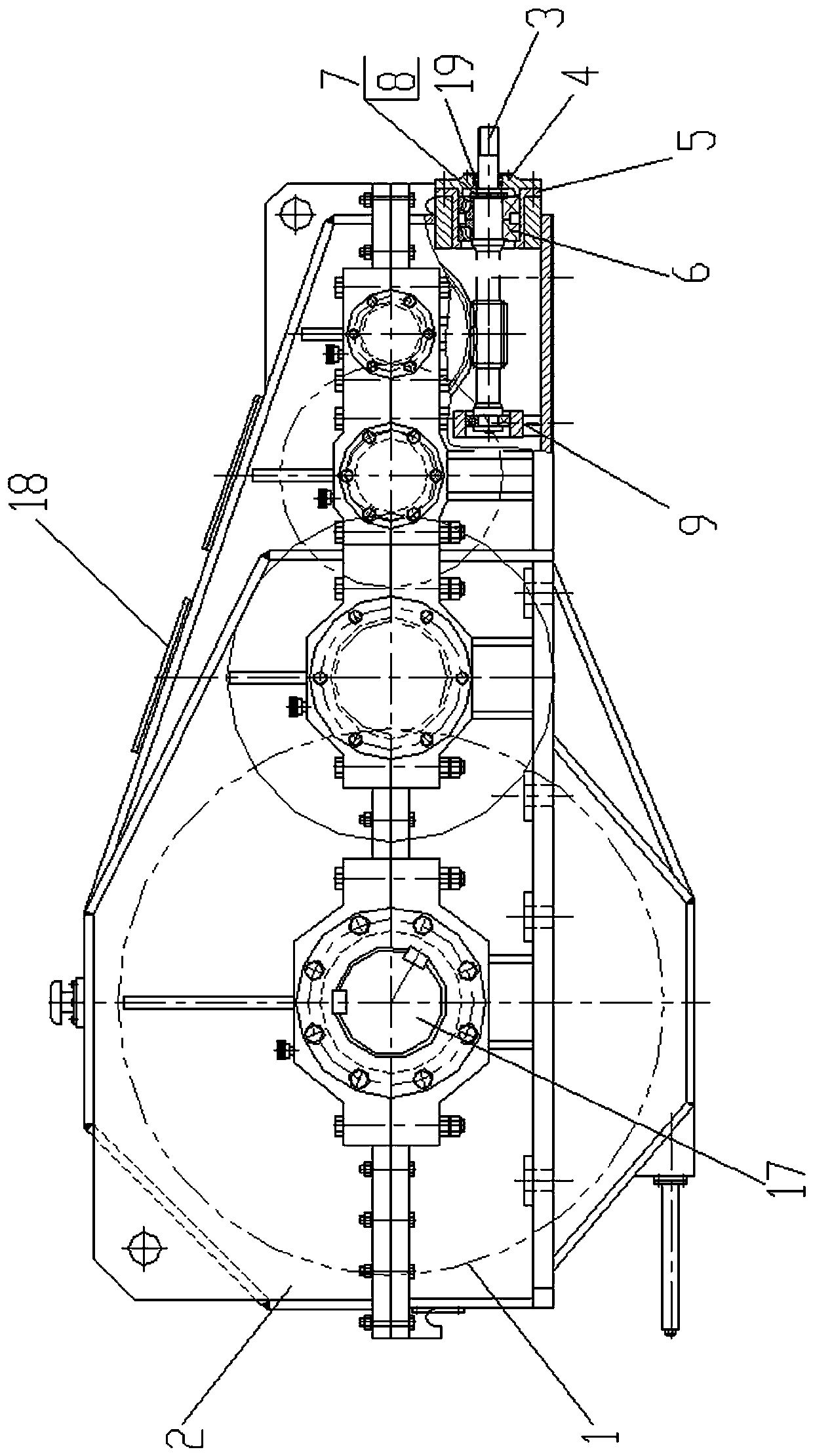
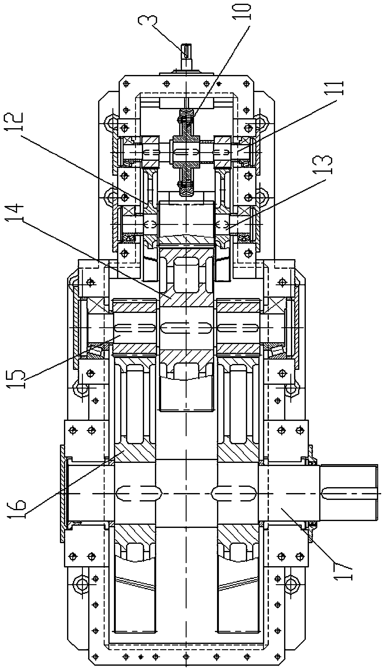
[0013] figure 1 , 2 Shown: a worm gear reducer used for walking in steel mills, including a lower box 1 and a box cover 2, the box cover seals the lower box to form a box, the box shrinks from left to right, and the box tilts to shrink There is a mirror hole 18 on the cover of the box, the right end of the lower box 1 is connected to the input worm 3, the input worm is supported on the right side of the lower box through the bearing seat 5 and the bearing 6, and the inner end of the input worm is supported by the support in the lower box On the seat 9, the inner side of the bearing is limited against the inner step on the input worm, and the outer side of the input worm is screwed to the outer side of the input worm through the stop washer 7 and the round nut 8 to lock and crimp the outer side of the bearing 6, and the outer side of the bearing is also threaded on the input worm The...


PUM


Abstract

The invention relates to a worm and gear gear reducer for travelling in a steel mill. A box body is obliquely shrunk from left to right, the right end part of a lower box body is connected with an input worm in a penetrating mode, a first-stage intermediate shaft, a second-stage intermediate shaft, a third-stage intermediate shaft and an output shaft are sequentially supported on the lower box body from right to left, the input worm meshes with a worm wheel on the first-stage intermediate shaft, the two ends, symmetrical about the worm wheel, of the first-stage intermediate shaft are in engaged transmission with the second-stage intermediate shaft through two first-stage gear sets, the second-stage intermediate shaft is in engaged transmission with the third-stage intermediate shaft through second-stage gear sets in the center positions of the two first-stage gear sets, and the two ends, symmetrical about the second-stage gear sets, of the third-stage intermediate shaft are in engagedtransmission with the output shaft through two third-stage gear sets, the output shaft extends out to be externally connected for output, and the first-stage gear sets, the second-stage gear sets andthe third-stage gear sets are gradually enlarged. The structure of the worm and gear gear reducer for the travelling in the steel mill is simple, directional power input and output are achieved, and meanwhile large torque and high load capacity are achieved.

Description

technical field [0001] The invention relates to a reducer, in particular to a worm gear reducer used for walking in steel mills. Background technique [0002] With the rapid development of my country's industrial technology, the requirements for reducers widely used in mechanical equipment in metallurgy, mining, chemical industry, construction, agriculture, transportation, power generation and other industries are getting higher and higher. In the operation process of existing steel mills, the reducer used in the automatic production line requires both directional power input and output, while ensuring a large torque and load capacity. If the reducer with the traditional standard structure transmission structure is used, it cannot Take into account the required power transmission. Contents of the invention [0003] The invention provides a worm and worm gear speed reducer for steel mills with simple structure, directional power input and output, high torque and high load ...

Claims


Application Information

Patent Timeline
IPC IPC(8): F16H57/021F16H57/022F16H57/039
CPCF16H57/021F16H57/022F16H57/039F16H2057/02069
Inventor 殷庆凤殷桂虎屈桂兰翁燕陆晓妹康宝刚蒋军张梅红
Owner JIANGSU TAILONG MACHINERY GRP CO CO LTD
Why Eureka
Try Eureka